
Quick Reference Version 6.06 User Manual

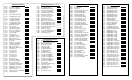


Alarm Codes
AIn Analog Input Signal Loss
HIdc High DC Bus Warning
I-Ac V/Hz Identification Active
I-En V/Hz Identification Enabled
LIL Low Input Line
S-Ac Vector Self-Tuning Active
S-En Vector Self-Tuning Enabled
Fault Codes
AIn Analog Input Signal Loss
bYC DC Bus Charging Bypass Not Closed
CHS Checksum Error
EC Earth Current Failure (Ground Fault)
EEr Non-volatile Memory Failure
EL Encoder Loss
FL Function Loss
HId V/Hz Identification Aborted
HIL High Input Line
HU High DC Bus Fault
IPL Input Phase Loss
LU Low DC Bus Fault
nCL Network Comm Loss
nId V/Hz Identification Not Performed
OC Overcurrent
OCA Overcurrent at Acceleration
OCb Overcurrent at DC Braking
OCd Overcurrent at Deceleration
OF Overfrequency
OH Drive Overtemperature
OL Motor Overload
OPL Motor Output Phase Loss
OSP Overspeed (Vector Only)
PUc Missing Power Module ID Connector
PUn Power Module Not Identified
PUo Power Module Overload
SF Vector Self-Tuning Aborted
Srl Serial Comm Lost
UAr PC Comm Spurious Interrupt
UbS Asymmetrical Bus Charge
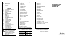
ATTENTION: This material is not intended
to provide operational instructions. Qualified
electrical personnel must read and
understand the applicable instruction
manuals in their entirety prior to installing,
adjusting, operating, and servicing this
equipment. Failure to observe this
precaution could result in severe bodily
injury or loss of life.
Printed in U.S.A. D-157-2 March 2001
Regulator Board Terminal Strip
1. RS-232 Transmit*
2. RS-232 Receive*
3. RS-232 Common*
4. Encoder +15 Volts
5. Encoder Phase A
6. Encoder Phase A Not
7. Encoder Phase B
8. Encoder Phase B Not
9. Encoder Common
10. Analog Meter Output
11. Analog Meter Common
12. Isolated Reference Voltage
13. Vdc Analog Speed Reference
14. mA Analog Speed Reference
15. Isolated Reference Ground
16. Digital Input +24 Volts
17. Digital Input 8 (Rem/Loc)
18. Digital Input 7 (Ramp1/Ramp2)
19. Digital Input 6 (Fwd/Rev)
20. Function Loss
21. Run/Jog
22. Reset
23. Stop
24. Start
25. +24 Vdc Common
26. Snubber Resistor Braking Output*
27. +24 Vdc Common*
28. N.C. Relay Contact**
29. N.C. Relay Common**
30. N.O. Relay Contact**
31. N.O. Relay Common**
*Not available on Bookshelf drives.
**Located on remote terminal strip on Bookshelf drives.
Refer to the following software (S/W) and hardware (H/W)
manuals for detailed information about the GV3000/SE AC
drive.
GV3000/SE Drive S/W I/M H/W I/M
1 to 400 HP @ 460 VAC D2-3359 D2-3360
75 to 200 HP @ 460 VAC D2-3391 D2-3392
1 to 20 HP @ 230 VAC D2-3387 D2-3388
30 to 100 HP @ 230 VAC D2-3416 D2-3417
2 to 30 A Bookshelf D2-3426 D2-3427
RMI Terminal Strip
41. Digital Input 1
42. Digital Input 2
43. Digital Input 3
44. Digital Input 4
45. Digital Input +24 Vdc
46. Digital Output External +24 Vdc
47. Digital Output 1
48. Digital Output 2
49. Digital Output 3
50. Digital Output 4
51. Digital Output Common
52. Relay 1 Common
53. Relay 1 N.O.
54. Relay 2 N.C.
55. Relay 2 Common
56. Relay 2 N.O.
57. Not Used
58. Relay 3 N.C.
59. Relay 3 Common
60. Relay 3 N.O.
61. Not Used
62. Analog Input 0 – 10 Vdc
63. Analog Input 0 – 20 mA
64. Analog Input Common
65. Analog Output 1: 0 to 10 Vdc
66. Analog Output 2: +/- 10 Vdc
67. Analog Output 3: 0 to 10 Vdc; 0 to 20 mA
68. Analog Output Common
69. Frequency Input: 0 to 200 kHz
Refer to the following manual for detailed information
about the Super Remote Meter Interface (RMI) board:
• D2-3341 Super Remote Meter Interface (RMI)
Board for use with GV3000/SE and
VTAC 7 Drives
GV3000/SE AC Drive
Quick Reference
Version 6.06
D-157-2