
Owner's manual
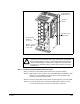
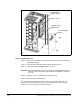
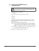
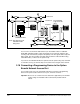
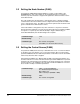
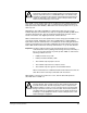
Table Of Contents
- GV3000/SE AC Drive ControlNet Network Communication Option Board
- List of Figures
- List of Tables
- Chapter 1 Introduction
- Chapter 2 Installation
- Table 2.1 - Locating the Appropriate Installation Procedure
- 1 HP
- 1V21xx
- 1V24xx
- 2.3
- 1 HP
- 1V41xx
- 1V44xx
- 2.1
- 2 HP
- 2V21xx
- 2V24xx
- 2.3
- 2 HP
- 2V41xx
- 2V44xx
- 2.1
- 3 HP
- 3V21xx
- 3V24xx
- 2.3
- 3 HP
- 3V41xx
- 3V44xx
- 2.1
- 5 HP
- 5V21xx
- 5V24xx
- 2.3
- 5 HP
- 5V41xx
- 5V44xx
- 2.1
- 7.5 HP
- 7V21xx
- 7V22xx
- 2.3
- 7.5 HP
- 7V41xx
- 7V42xx
- 2.2
- 10 HP
- 10V21xx
- 10V22xx
- 2.3
- 10 HP
- 10V41xx
- 10V42xx
- 2.2
- 15 HP
- 15V21xx
- 15V22xx
- 2.3
- 15 HP
- 15V41xx
- 15V42xx
- 2.5
- 20 HP
- 20V21xx
- 20V22xx
- 2.3
- 20 HP
- 20V41xx
- 20V42xx
- 2.5
- 25 HP
- 25G41xx
- 25G42xx
- 25V41xx
- 25V42xx
- 2.5
- 30 HP
- 30V20xx
- 2.4
- 30 HP
- 30V41xx
- 30V42xx
- 2.5
- 40 HP
- 40V20xx
- 2.4
- 40 HP
- 40V41xx
- 40V42xx
- 2.5
- 50 HP
- 50R41xx
- 2.6
- 50 HP
- 50T41xx
- 2.6
- 50 HP
- 50V20xx
- 2.4
- 50 HP
- 50V41xx
- 50V42xx
- 2.5
- 60 HP
- 60G41xx
- 60G42xx
- 2.5
- 60 HP
- 60V20xx
- 2.4
- 75 HP
- 75R41xx
- 2.6
- 75 HP
- 75T41xx
- 2.6
- 75 HP
- 75V20xx
- 2.4
- 75 HP
- 75V40xx
- 2.4
- 100 HP
- 100V20xx
- 2.4
- 100 HP
- 100V40xx
- 2.4
- 125 HP
- 125R41xx
- 2.6
- 125 HP
- 125V40xx
- 2.4
- 150 HP
- 150V40xx
- 2.4
- 200 HP
- 200V40xx
- 2.4
- 200 HP
- 200V41xx
- 2.7
- 250 HP
- 250V41xx
- 2.7
- 300 HP
- 300V41xx
- 2.7
- 350 HP
- 350V41xx
- 2.7
- 400 HP
- 400V41xx
- 2.7
- 2 to 15 Amp
- 31ER40xx
- 31ET40xx
- 38ER40xx
- 38ET40xx
- 55ER40xx
- 55ET40xx
- 85ER40xx
- 85ET40xx
- 126ER40xx
- 126ET40xx
- 150ER40xx
- 150ET40xx
- 2.8
- 24 to 30 Amp
- 240ER40xx
- 240ET40xx
- 300ER40xx
- 300ET40xx
- 2.8
- 43 Amp
- 430ER40xx
- 430ET40xx
- 2.8
- 2.1 Installing the ControlNet Option Board in 1 to 5 HP @ 460 VAC Drives
- Use this procedure to install the ControlNet option board in the drives listed in table 2.2.
- Table 2.2 - Model Numbers for 1 to 5 HP @ 460 VAC Drives
- Step 1. Shut Down the Drive
- Step 2. Verify that the DC Bus Capacitors are Discharged
- Step 3. Remove the Keypad Bracket from the Drive
- Step 3.1 Record connections to the Regulator board terminal strip if they must be disconnected to remove the keypad bracket.
- Step 3.2 Use a magnetic screwdriver to remove the three M4 x 10 screws that fasten the bottom of the keypad support bracket to the drive heat sink.
- Step 3.3 Spread the retaining clips on the 26-conductor Regulator board ribbon cable connector to disconnect it from the Current Feedback board. The Current Feedback board is located on the right below the keypad.
- Step 3.4 Move the keypad support bracket aside.
- Step 3.5 Pinch the retaining clip that is through the center of the Current Feedback board and carefully pull out the Current Feedback board.
- Step 3.6 Unplug the internal fan assembly power connector (CONN7) from the drive.
- Step 4. Install the ControlNet Option Board in the Keypad Bracket
- Refer to figure 2.2 for component locations.
- Side View
- Figure 2.2 - 1 to 5 HP @ 460 VAC GV3000/SE Drive
- Step 4.1 Remove the ControlNet option board from its anti-static wrapper.
- Step 4.2 Align the key on the connector of the ControlNet option board ribbon cable with the key on the Regulator board connector. Press the ribbon cable connector in until it locks into position.
- Step 4.3 Route the 26-conductor ribbon cable for the Current Feedback board out of the side of the keypad bracket.
- Step 4.4 Align the ControlNet option board on the four mounting tabs on the keypad bracket. Make sure that the ribbon cable is not pinched between the keypad bracket and the ControlNet option board.
- Step 4.5 Fasten the right side of the ControlNet option board to the keypad bracket. Use the two metal M3 screws and lock washers for grounding.
- Step 4.6 Fasten the left side of the ControlNet option board to the keypad bracket using the two plastic rivets.
- Step 5. Reinstall the Keypad Bracket in the Drive
- Step 5.1 Reconnect the internal fan assembly power connector (CONN7) to the drive. Align the key on the connector with the slot in the receptacle. Press the connector into position.
- Step 5.2 Reinstall the Current Feedback board. Carefully align the two sets of connector pins on the Current Feedback board with...
- Step 5.3 Inspect the Current Feedback board connector thoroughly for bent or misaligned pins.
- Step 5.4 Align the keypad support bracket with the mounting holes in the drive heat sink. Fasten the bracket with the three M4 x 10 screws removed earlier.
- Step 5.5 Align the Regulator board’s 26-conductor ribbon cable connector with the Current Feedback board connector. Press it in until it locks into position.
- Step 5.6 Route the Network Drop Cable through the left-most opening at the bottom of the drive.
- Step 5.7 Connect the brown wire to terminal 1 of the 2-connector terminal strip. Connect the white wire to terminal 2.
- Step 5.8 Reconnect any wiring that was removed from the Regulator board.
- Step 5.9 NEMA 4X/12 drives only: Before installing the cover, check that the gaskets on the cover are flat and within the gasket channels.
- Step 5.10 Reinstall the cover. Align all cover screws into the heat sink before tightening any of them.
- 2.2 Installing the ControlNet Option Board in 7.5 to 10 HP @ 460 VAC Drives
- Use this procedure to install the ControlNet option board in drives with model numbers 7V41xx, 7V42xx, 10V41xx, or 10V42xx.
- Unless otherwise indicated, keep all hardware that is removed. You will need it for reassembly. This includes screws, lock washers, and rivets.
- Step 1. Shut Down the Drive
- Step 2. Verify that the DC Bus Capacitors are Discharged
- Step 3. Remove the Keypad Bracket from the Drive
- Step 3.1 Record connections to the Regulator board terminal strip if they must be disconnected to remove the keypad bracket.
- Step 3.2 Loosen the thumb screw on the left side of the keypad bracket. Hold the bracket on the left and lift the bracket up and to the left to separate it from the keypad support bracket.
- Step 3.3 Spread the retaining clips on the 26-conductor Regulator board ribbon cable connector to disconnect it from the Current Feedback board. The Current Feedback board is located on the right below the keypad.
- Step 4. Install the ControlNet Option Board in the Keypad Bracket
- Refer to figure 2.4 for component locations.
- Side View
- Figure 2.4 - 7.5 to 10 HP @ 460 VAC GV3000/SE Drive
- Step 4.1 Remove the ControlNet option board from its anti-static wrapper.
- Step 4.2 Align the key on the connector of the ControlNet option board ribbon cable with the key on the Regulator board connector. Press the ribbon cable connector in until it locks into position.
- Step 4.3 Route the 26-conductor ribbon cable for the Current Feedback board out of the side of the keypad bracket.
- Step 4.4 Align the ControlNet option board on the four mounting tabs on the keypad bracket. Make sure that the ribbon cable is not pinched between the keypad bracket and the ControlNet option board.
- Step 4.5 Fasten the right side of the ControlNet option board to the keypad bracket. Use the two metal M3 screws and lock washers for grounding.
- Step 4.6 Fasten the left side of the ControlNet option board to the keypad bracket using the two plastic rivets.
- Step 4.7 Reconnect the keypad bracket to the keypad support bracket by inserting the mounting tabs into the slots in the support bracket and tightening the thumb screw.
- Step 4.8 Align the Regulator board’s 26-conductor ribbon cable connector with the Current Feedback board connector. Press it in until it locks into position.
- Step 5. Reinstall the Keypad Support Bracket in the Drive
- Step 5.1 Route the Network Drop Cable through the left-most opening at the bottom of the drive.
- Step 5.2 Connect the brown wire to terminal 1 of the 2-connector terminal strip. Connect the white wire to terminal 2.
- Step 5.3 Reconnect any wiring that was removed from the Regulator board.
- Step 5.4 NEMA 4X/12 drives only: Before installing the cover, check that the gaskets on the cover are flat and within the gasket channels.
- Step 5.5 Reinstall the cover. Align all cover screws into the heat sink before tightening any of them.
- 2.3 Installing the ControlNet Option Board in 1 to 20 HP @ 230 VAC Drives
- Table 2.3 - Model Numbers for 1 to 20 HP @230 VAC Drives
- Step 1. Shut Down the Drive
- Step 2. Verify that the DC Bus Capacitors are Discharged
- Step 3. Remove the Keypad Bracket from the Drive
- Step 3.1 Record connections to the Regulator board terminal strip if they must be disconnected to remove the keypad bracket.
- Step 3.2 Use a magnetic screwdriver to remove the M4 x 10 screws that fasten the bottom of the keypad support bracket to the drive heat sink.
- Step 3.3 Spread the retaining clips on the Regulator board ribbon cable (on the right side) to disconnect it from the Base Board.
- Step 3.4 Remove the keypad bracket. Place it with the keypad down on a flat surface. If you cannot lay it flat, tie it up to prevent damage to wiring.
- Step 4. Install the ControlNet Option Board in the Keypad Bracket
- Step 4.1 Remove the ControlNet option board from its anti-static wrapper.
- Step 4.2 Align the key on the connector of the ControlNet option board ribbon cable with the key on the Regulator board connector. Press the ribbon cable connector in until it locks into position.
- Step 4.3 Route the other ribbon cable out of the side of the keypad bracket.
- Step 4.4 Align the ControlNet option board on the four mounting tabs on the keypad bracket. Make sure that the ribbon cable is not pinched between the keypad bracket and the ControlNet option board.
- Step 4.5 Fasten the right side of the ControlNet option board to the keypad bracket. Use the two metal M3 screws and lock washers for grounding.
- Step 4.6 Fasten the left side of the ControlNet option board to the keypad bracket using the two plastic rivets.
- Figure 2.6 - 1 to 20 HP @ 230 VAC GV3000/SE Drive
- Step 5. Reinstall the Keypad Bracket in the Drive
- Step 5.1 Place the keypad support bracket back into position. Use a magnetic screwdriver to fasten it to the heatsink with the screws removed earlier.
- Step 5.2 Realign the 26-conductor ribbon cable connector with the connector inside the slot in the keypad support bracket. Carefully press the ribbon cable connector in until the retaining clips lock into place.
- Step 5.3 Route the Network Drop Cable through the left-most opening at the bottom of the drive.
- Step 5.4 Connect the brown wire to terminal 1 of the 2-connector terminal strip. Connect the white wire to terminal 2.
- Step 5.5 Reconnect any wiring that was removed from the Regulator board.
- Step 5.6 NEMA 4X/12 drives only: Before installing the cover, check that the gaskets on the cover are flat and within the gasket channels.
- Step 5.7 Reinstall the cover. Align all cover screws into the heat sink before tightening any of them.
- 2.4 Installing the ControlNet Option Board in 30 to 100 HP @ 230 VAC and 75 to 200 HP@460 VAC Drives
- Table 2.4 - Model Numbers for 30 to 100 HP @ 230 VAC and 75 to 200 HP@460 VAC Drives
- Step 1. Shut Down the Drive
- Step 2. Verify that the DC Bus Capacitors are Discharged
- Step 2.1 Use a voltmeter to verify that there is no voltage at the drive’s AC input power terminals (R/L1, S/L2, T/L3).
- Step 2.2 Ensure that the DC bus capacitors are discharged. To check DC bus potential:
- Figure 2.7 - DC Bus Voltage Terminals (30 to 100 HP @ 230 VAC and 75 to 200 HP @ 460 VAC Drives)
- Step 3. Remove the Keypad Bracket from the Drive
- Step 3.1 If the drive has:
- Figure 2.8 - Location of Terminal Cover and Regulator Board Cover in 75 to 200 HP (460 VAC) and 30 to 100 HP (230 VAC) Drives
- Step 3.2 Record connections to the Regulator board terminal strip if they must be disconnected to remove the keypad bracket.
- Step 3.3 Remove the terminal cover, which is below the keypad and fastened with two M4 screws. See figure 2.8.
- Step 3.4 Pull the keypad assembly partly out of the drive. Spread the retaining clips on the Regulator board ribbon cable (on the right side) to disconnect it from the Base Board. See figure 2.9.
- Step 3.5 Remove the keypad bracket. Place it with the keypad down on a flat surface. If you cannot lay it flat, tie it up to prevent damage to wiring.
- Figure 2.9 - Regulator Board’s Connections to Option Board, Keypad, and Base Board
- Step 4. Install the ControlNet Option Board in the Keypad Bracket
- Step 4.1 Remove the ControlNet option board from its anti-static wrapper.
- Step 4.2 Align the key on the connector of the ControlNet option board ribbon cable with the key on the Regulator board connector. Press the ribbon cable connector in until it locks into position.
- Step 4.3 Route the other ribbon cable out of the side of the keypad bracket.
- Step 4.4 Align the ControlNet option board on the four mounting tabs on the keypad bracket. Make sure that the ribbon cable is not pinched between the keypad bracket and the ControlNet option board.
- Step 4.5 Fasten the right side of the ControlNet option board to the keypad bracket. Use the two metal M3 screws and lock washers for grounding.
- Step 4.6 Fasten the left side of the ControlNet option board to the keypad bracket using the two plastic rivets.
- Step 5. Reinstall the Keypad Bracket in the Drive
- Step 5.1 Align the Regulator board ribbon cable connector with the connector to the Base board. Carefully press the ribbon cable connector in until the retaining clips lock into place.
- Step 5.2 Place the keypad bracket back into position.
- Step 5.3 If the drive has:
- Step 5.4 Route the Network Drop Cable through the left-most opening at the bottom of the drive.
- Step 5.5 Connect the brown wire to terminal 1 of the 2-connector terminal strip. Connect the white wire to terminal 2.
- Step 5.6 Reconnect any wiring that was removed from the Regulator board.
- Step 5.7 Replace the terminal cover (below the keypad). Fasten it using the two M4 screws removed earlier.
- 2.5 Installing the ControlNet Option Board in 15 to 25 HP and 25 to 60 HP @ 460 VAC Drives
- Use this procedure to install the ControlNet option board in drives with the model numbers listed in table 2.5.
- Table 2.5 - Model Numbers for 15 to 60 HP @460 VAC Drives
- Step 1. Shut Down the Drive
- Step 2. Verify that the DC Bus Capacitors are Discharged
- Step 2.1 Use a voltmeter to verify that there is no voltage at the drive’s AC input power terminals (R/L1, S/L2, T/L3).
- Step 2.2 Ensure that the DC bus capacitors are discharged. To check DC bus potential:
- Figure 2.10 - DC Bus Voltage Terminals (15 to 25 HP @ 460 VAC)
- Figure 2.11 - DC Bus Voltage Terminals (25 to 60 HP @ 460 VAC)
- Step 3. Remove the Keypad Bracket from the Drive
- Step 3.1 Record connections to the Regulator board terminal strip if they must be disconnected to remove the keypad bracket.
- Step 3.2 Loosen the thumb screw on the left side of the keypad bracket. Hold the bracket on the left and lift the bracket up and to the left to separate it from the keypad support bracket.
- Step 3.3 Disconnect the 26-conductor Regulator board ribbon cable from the Power Supply board (located on the right side below t...
- Network Option Board
- Network Option Board
- Figure 2.12 - GV3000/SE Drive (15 to 25 and 25 to 60 HP @ 460 VAC)
- Step 4. Install the ControlNet Option Board in the Keypad Bracket
- Refer to figure 2.12 for component locations.
- Step 4.1 Remove the ControlNet option board from its anti-static wrapper.
- Step 4.2 Align the key on the connector of the ControlNet option board ribbon cable with the key on the Regulator board connector. Press the ribbon cable connector in until it locks into position.
- Step 4.3 Align the ControlNet option board on the four mounting tabs on the keypad bracket. Make sure that the ribbon cable is not pinched between the keypad bracket and the ControlNet option board.
- Step 4.4 Fasten the right side of the ControlNet option board to the keypad bracket. Use the two metal M3 screws and lock washers for grounding.
- Step 4.5 Fasten the left side of the ControlNet option board to the keypad bracket using the two plastic rivets.
- Step 4.6 Realign the 26-conductor ribbon cable connector with the Power Supply board connector inside the slot in the keypad support bracket. Carefully press the ribbon cable connector in until the retaining clips lock it into place.
- Refer to figure 2.12 for component locations.
- Step 5. Reinstall the Keypad Bracket in the Drive
- Step 5.7 Reconnect the keypad bracket to the keypad support bracket by inserting the mounting tabs into the slots in the support bracket and tightening the thumb screw.
- Step 5.8 Route the Network Drop Cable through the left-most opening at the bottom of the drive.
- Step 5.9 Connect the brown wire to terminal 1 of the 2-connector terminal strip. Connect the white wire to terminal 2.
- Step 5.10 Reconnect any wiring that was removed from the Regulator board.
- Step 5.11 NEMA 4X/12 drives only: Before installing the cover, check that the gaskets on the cover are flat and within the gasket channels.
- Step 5.12 Reinstall the cover. Align all cover screws into the heat sink before tightening any of them.
- 2.6 Installing the ControlNet Option Board in 50 to 100 HP and 100 to 150 HP @ 460 VAC Drives
- Use this procedure to install the ControlNet option board in drives with the model numbers 50R41xx, 50T41xx, 75R41xx, 75T41xx, or 125R41xx.
- Step 1. Shut Down the Drive
- Step 2. Verify that the DC Bus Capacitors are Discharged
- Step 2.1 Use a voltmeter to verify that there is no voltage at the drive’s AC input power terminals (1L1, 1L2, 1L3).
- Step 2.2 Ensure that the DC bus capacitors are discharged. To check DC bus potential:
- a. Stand on a non-conductive surface and wear insulated gloves.
- b. 50 to 100 HP @ 460 V only: Use a voltmeter to measure the DC bus potential at the diode bridge. Refer to figure 2.13.
- c. 100 to 150 HP @ 460 V only: Take care not to touch any conductive traces. Use a voltmeter to measure the DC bus potential at the bottom of the fuse holders on the Power Module Interface board on the back of the Regulator panel. Refer to figure 2.14.
- Figure 2.13 - 50 to 100 HP Drive Components and Locations
- Step 3. Remove the Keypad Bracket from the Drive
- Step 3.1 Loosen the two screws from the top of the hinged panel (where the keypad bracket is mounted). Tilt the mounting panel forward out of the drive chassis.
- Step 3.2 Record connections to the Regulator board terminal strip if they must be disconnected to remove the keypad bracket.
- Step 3.3 Spread the retaining clips on the Regulator board’s 60-conductor ribbon cable connector to disconnect it from the Power...
- Step 3.4 Use a magnetic screwdriver to remove the four screws and lock washers that fasten the keypad bracket to the hinged mounting panel. Hold the keypad bracket as you remove the screws.
- Step 4. Install the ControlNet Option Board in the Keypad Bracket
- Step 4.1 Remove the ControlNet option board from its anti-static wrapper.
- Step 4.2 Align the key on the connector of the ControlNet option board ribbon cable with the key on the Regulator board connector. Press the ribbon cable connector in until it locks into position.
- Step 4.3 Align the ControlNet option board on the four mounting tabs on the keypad bracket. Make sure that the ribbon cable is not pinched between the keypad bracket and the ControlNet option board.
- Step 4.4 Fasten the right side of the ControlNet option board to the keypad bracket. Use the two metal M3 screws and lock washers for grounding.
- Step 4.5 Fasten the left side of the ControlNet option board to the keypad bracket using the two plastic rivets.
- Figure 2.14 - 100 to 150 HP Drive Components and Locations
- Step 5. Reinstall the Keypad Bracket in the Drive
- Step 5.1 Reconnect the keypad bracket to the hinged mounting panel using the four screws and lock washers removed earlier.
- Step 5.2 100 to 150 HP drives only: Remove the tie that was fastened to the Power Module Interface board earlier.
- Step 5.3 100 to 150 HP drives only: Align the Power Module Interface board on the eight plastic standoffs on the back of the mounting panel. Carefully press it into place. Make sure that good contact has been made with the two grounding standoffs.
- Step 5.4 Route the Regulator board’s 60-conductor ribbon cable through the slot in the hinged mounting panel to the connector on...
- Step 5.5 Swing the hinged mounting panel back into position. Make sure no wires or cables are pinched by the panel.
- Step 5.6 Refasten the two screws at the top of the panel.
- Step 5.7 Route the Network Drop Cable through the right-most opening at the bottom of the drive, away from the AC lines.
- Step 5.8 Connect the brown wire to terminal 1 of the 2-connector terminal strip. Connect the white wire to terminal 2.
- Step 5.9 Reconnect any wiring that was removed from the Regulator board.
- Step 5.10 Replace mounting panel and fasten with two screws at the top of the hinged panel (where the keypad bracket is mounted).
- Step 5.11 NEMA 4X/12 drives only: Before installing the cover, check that the gaskets on the cover are flat and within the gasket channels.
- Step 5.12 Reinstall the cover with the six screws removed in step 1.3. Make sure no wires or cables are pinched by the cover.
- 2.7 Installing the ControlNet Option Board in 200 to 400 HP @ 460 VAC Drives
- Use this procedure to install the ControlNet option board in drives with part number 200V41xx, 250V41xx, 300V41xx, 350V41xx, or 400V41xx.
- Step 1. Shut Down the Drive
- Step 2. Verify that the DC Bus Capacitors are Discharged
- Step 2.1 Open the drive’s outer cabinet door.
- Step 2.2 Lower the plastic terminal strip shield at the top of the drive.
- Step 2.3 Use a voltmeter to verify that there is no voltage at the drive’s AC input power terminals, R, S, and T.
- Step 2.4 Replace the plastic terminal strip shield.
- Step 2.5 Ensure that the DC bus capacitors are discharged. To check DC bus potential:
- Step 3. Remove the Keypad Bracket from the Drive
- Refer to figure 2.15 for component locations.
- Network Option Board
- Figure 2.15 - GV3000/SE Drive (200 to 400 HP)
- Step 3.1 Record connections to the Regulator board terminal strip if they must be disconnected to remove the keypad bracket.
- Step 3.2 Use a magnetic screwdriver to remove the four screws and lock washers that fasten the keypad bracket to the hinged mounting panel. Hold the keypad bracket as you remove the screws.
- Step 3.3 Disconnect the Regulator board ribbon cable from the Power Module Interface board.
- Step 4. Install the ControlNet Option Board
- Step 4.1 Remove the ControlNet option board from its anti-static wrapper.
- Step 4.2 Align the ControlNet option board’s four mounting holes with the four standoffs on the hinged mounting panel of the drive.
- Step 4.3 Fasten the board to the drive with four ² nuts. Metal nuts must be used for proper grounding of the ControlNet option board.
- Step 4.4 Connect the brown wire to terminal 1 of the 2-connector terminal strip. Connect the white wire to terminal 2.
- Step 4.5 Align the key on the connector of the ControlNet option board ribbon cable with the key on the Regulator board connector. Press the ribbon cable connector in until it locks into position.
- Step 4.6 Route the Network Drop Cable through the signal wiring tray on the right side of the drive.
- Step 5. Reinstall the Keypad Bracket in the Drive
- Step 5.1 Align the key on the connector from the Regulator board with the key of the connector on the Power Module Interface board. Press the ribbon cable connector in until it locks into position.
- Step 5.2 Reconnect the keypad bracket to the hinged mounting panel using the four screws removed earlier.
- Step 5.3 Reconnect any wiring that was removed from the Regulator board.
- Step 5.4 Close and secure the outer cabinet door of the drive.
- 2.8 Installing the ControlNet Option Board in 2 to 43 Amp GV3000/SE Bookshelf Drives
- Table 2.6 - Model Numbers for 2 to 15 Amp and 24 to 43 Amp Drives
- Step 1. Shut Down the Drive
- Step 1.1 Disconnect, lock out, and tag all incoming power to the drive.
- Step 1.2 Wait five minutes for the DC bus capacitors to discharge.
- Step 1.3 Disconnect all faceplate wiring.
- Step 1.4 Remove the cover as follows:
- a. Unscrew the attaching screw on the cover.
- b. Lift the cover and carefuly take it out of the heatsink as far as the flat ribbon keypad cable will allow. This cable connects the display with the Regulator board.
- c. Use a screwdriver to slide the cable out of the connector on the Regulator board to competely detach the cover.
- Step 1.5 24 to 43 A drives only: Remove the front panel by unscrewing the two attaching screws.
- Step 2. Verify that the DC Bus Capacitors are Discharged
- Step 2.1 Use a voltmeter to verify that there is no voltage at the drive’s AC input power terminals (R/L1, S/L2, T/L3). Refer to figure 2.16 or 2.19 for the location of these terminals.
- Step 2.2 Ensure that the DC bus capacitors are discharged. To check DC bus potential:
- Step 2.3 24 to 43 A drives only: Reattach the front panel after checking the DC bus potential.
- Figure 2.16 - 2 to 15 Amp GV3000/SE Bookshelf Drives
- Figure 2.17 - 24 to 30 Amp GV3000/SE Bookshelf Drives
- Figure 2.18 - 43 Amp GV3000/SE Bookshelf Drives
- Figure 2.19 - 24 to 30 Amp GV3000/SE Bookshelf Drive (Cover and Front Panel Removed)
- Step 3. Install the ControlNet Option Board in the Drive
- Step 3.1 Remove the ControlNet option board from its anti-static wrapper.
- Step 3.2 Align the key on the connector of the ControlNet option board ribbon cable with the key on the Regulator board connector. Press the ribbon cable connector in until it locks into position.
- Step 3.3 Fasten the ControlNet option board to the drive using the screws provided.
- Step 3.4 Connect the brown wire of the Network Drop Cable to terminal 1 of the 2-connector terminal strip. Connect the white wire to terminal 2.
- Figure 2.20 - Installing the ControlNet Option Board
- Step 4. Reattach the Cover
- Step 4.1 Remove enough tabs on the faceplate breakout panel to allow the Network Drop Cable through.
- Step 4.2 Route the Network Drop Cable through the breakout panel.
- Step 4.3 Reconnect the keypad/display cable to the cover.
- Step 4.4 Reattach the cover using the single faceplate screw.
- Step 4.5 Reconnect all faceplate wiring.
- 2.9 Connecting the GV3000/SE Drive to a ControlNet Network
- Step 4.1 Stop any application tasks that are running.
- Step 4.2 Remove the lockout and tag. Apply power to the drive. SELF is displayed while the drive performs power-up diagnostics. If there is an error during diagnostics, it is logged. See your drive software manual for information on errors.
- Step 4.3 Connect a ControlNet Network drop cable to one of the BNC connectors on the option board. Connect the other end to a tap.
- Figure 2.21 - Connecting a GV3000/SE Drive to the ControlNet Network
- 2.10 Connecting a Programming Device to the Option Board’s Network Access Port
- Table 2.1 - Locating the Appropriate Installation Procedure
- Chapter 3 Setting Up the GV3000/SE Drive
- 3.1 Setting the Control Type (P.048)
- 3.2 Setting the Node Number (P.060)
- 3.3 Setting the Control Source (P.000)
- 3.4 Setting the Run/Program Response (P.061)
- 3.5 Setting the Communication Loss Response (P.062)
- 3.6 Setting the Network Output Register Sources P.066 to P.069)
- 3.7 Option Port: Type and Version (P.065)
- 3.8 Network Reference Source (P.063) and Network Trim Reference Source (P.064)
- Chapter 4 Programming the Drive
- 4.1 About ControlNet Network Communication
- 4.2 Configuring Drive Reference and Feedback Data as Scheduled Transfers
- 4.3 Using Unscheduled Transfers
- 4.3.1 Programming the MSG Instruction in a PLC-5
- 4.3.2 About MSG Instruction Timing
- 4.3.3 About the Files You Can Access
- 4.3.4 Using the Drive Parameters Data (N10:X)
- 4.3.5 Using the Drive Display Data (N11:X)
- 4.3.6 Using the Drive Reference and Feedback Data (N12:X)
- 4.3.7 Using the Write Status File (N20:X) to Troubleshoot a Drive Parameter Write Command
- Chapter 5 Configuring ControlLogix Applications
- Figure 5.1 - RSLogix 5000: I/O Configuration Selection
- Step 1. Right-click on the I/O Configuration folder and select New Module (figure 5.2).
- Figure 5.2 - RSLogix 5000: New Module Selection
- Step 2. Select the ControlNet module used by the controller. In this example (figure 5.3), a 1756-CNB Series B ControlNet Bridge is selected.Click OK.
- Step 3. Enter a Name, Slot number, and Revision number (figure 5.4). Click Next>.
- Step 4. This step is used to define controller-to-module behavior (figure 5.5). Inhibit Module inhibits/un-inhibits the connecti...
- Step 5. This window (figure 5.6) is displayed for informational purposes only. Click Next>.
- Step 6. This window (figure 5.7) is displayed for informational purposes only. Click Finish>>.
- Step 7. The 1756-CNB/B now appears in the I/O Configuration folder (figure 5.8).
- Step 8. Right-click on the 1756-CNB and select New Module (figure 5.9).
- Step 9. To configure a GV3000 drive, select the GV300 (figure 5.10). Click OK.
- Step 10. Enter a Name, Node number, and Revision number (figure 5.11). Click Next>.
- Step 11. The Requested Packet Interval (RPI) schedules the connection to move data to or from the module at least this often or the connection will fail with the RPI Not Valid error. Set this value to 5 ms or greater, and click Next> (figure 5.12).
- Step 12. This window (figure 5.13) is for informational purposes only. Click Finish>>.
- Step 13. The configured node (“GV3000” in this example) now appears under the 1756-CNB module in the I/O Configuration folder.
- Step 14. Repeat the previous steps for each additional node you need to configure.
- Step 15. In the Data Types folder, click on the Module-Defined sub-folder. When you create a module, module-defined data types a...
- Step 16. Select Communications / Download to download the configuration to the controller (figure 5.16). RSLogix automatically enters on-line mode when complete.
- Step 17. An Attention symbol is located next to the Node 2 (GV3000) icon in figure 5.17, which indicates the ControlNet scanner needs to be configured.
- Step 18. Start RSNetWorx and perform the following:
- a. Click the On-line icon and browse the network.
- b. Select Edits Enabled and view the messages in the Message View for completion (figure 5.18). The icon should disappear from the nodes in the Graphical View.
- c. Select File / Save and save the project.
- d. Close RSNetworx.
- Chapter 6 Configuring SLC500 Applications
- 6.1 Required Software and Equipment
- Table 6.1 - Required Software and Equipment
- RSLinx Software
- RSNetWorx for ControlNet software
- RSLogix 500 software
- SLC 500 Chassis w/appropriately sized Power Supply
- SLC 5/03 processor (1747-L532)
- or SLC 5/04 processor
- ControlNet Scanner Module: 1747-SCNR
- ControlNet RS-232 Interface: 1747-KFC15
- PC with 1784-KXTC15 or 1784-PCIC interface card
- GV3000 ControlNet Communications Board (2CN3000)
- Version 2.20 or later
- Version 2.25 or later
- Version 3.01 or later
- OS 301 or higher
- Any OS
- Version 2.20 or later
- Table 6.1 - Required Software and Equipment
- 6.2 Network Configuration
- 6.3 1747-KFC15 Set Up
- 6.4 Scheduled Messaging (I/O)
- 6.5 Unscheduled Messaging
- 6.6 SLC500 Support
- 6.1 Required Software and Equipment
- Chapter 7 Register Map
- Table 7.1 - File N10:X (Drive Read/Write Parameters)
- H Parameters
- U Parameters
- P.000
- P.001
- P.002
- P.003
- P.004
- P.005
- P.006
- P.007
- P.008
- P.009
- P.010
- P.011
- P.012
- P.013
- P.014
- P.015
- P.016
- P.017
- P.018
- P.019
- P.020
- P.021
- P.022
- P.023
- P.024
- P.025
- P.026
- P.027
- P.028
- P.029
- P.030
- P.031
- P.032
- P.033
- P.034
- P.035
- P.036
- P.037
- P.038
- P.039
- P.040
- P.041
- P.042
- P.043
- P.044
- P.045
- P.046
- P.047
- P.048
- P.049
- P.050
- P.051
- P.052
- P.053
- P.054
- P.055
- P.056
- P.057
- P.058
- P.059
- P.060
- P.061
- P.062
- P.063
- P.064
- P.065
- P.066
- P.067
- P.068
- P.069
- P.070
- |
- P.089
- P.090
- P.091
- P.0920
- P.093
- P.094
- P.095
- P.096
- P.097
- P.098
- P.099
- H.000
- H.001
- H.002
- H.003
- H.004
- H.005
- H.006
- H.007
- H.008
- H.009
- H.010
- H.011
- H.012
- H.013
- H.014
- H.015
- H.016
- H.017
- H.018
- H.019
- H.020
- H.021
- H.022
- U.000
- U.001
- U.002
- U.003
- U.004
- U.005
- U.006
- U.007
- U.008
- U.009
- U.010
- U.011
- U.012
- U.013
- U.014
- U.015
- U.016
- U.017
- U.018
- U.019
- U.020
- U.021
- U.022
- U.023
- U.024
- U.025
- U.026
- U.027
- U.028
- U.029
- U.030
- U.031
- U.032
- U.033
- U.034
- U.035
- U.036
- U.037
- U.038
- U.039
- U.040
- U.041
- U.042
- U.043
- U.044
- U.045
- U.046
- U.047
- U.048
- Configurable
- Tunable
- Tunable
- Tunable
- Tunable
- Tunable
- Tunable
- Configurable
- Configurable
- Tunable
- Tunable
- Configurable
- Tunable
- Configurable
- Configurable
- Tunable
- Tunable
- Tunable
- Tunable
- Configurable
- Tunable
- Tunable
- Tunable
- Tunable
- Tunable
- Tunable
- Tunable
- Tunable
- Tunable
- Read Only
- Tunable
- Tunable
- Tunable
- Tunable
- Tunable
- Tunable
- Tunable
- Tunable
- Tunable
- Configurable
- Configurable
- Configurable
- Configurable
- Configurable
- Tunable
- Configurable
- Configurable
- Configurable
- Tunable
- Tunable
- Tunable
- Configurable
- Tunable
- Read Only
- Configurable
- Tunable
- Read Only
- Tunable
- Tunable
- Tunable
- Tunable
- Tunable
- Read Only
- Read Only
- Read Only
- Read Only
- Configurable
- Configurable
- Configurable
- Configurable
- Tunable
- Tunable
- Tunable
- Tunable
- Tunable
- Tunable
- Tunable
- Tunable
- Tunable
- Tunable
- Tunable
- Tunable
- Configurable
- Configurable
- Configurable
- Read Only
- Configurable
- Configurable
- Configurable
- Configurable
- Configurable
- Configurable
- Configurable
- Configurable
- Configurable
- Configurable
- Configurable
- Configurable
- Read Only
- Tunable
- Tunable
- Tunable
- Tunable
- Configurable
- Configurable
- Configurable
- Tunable
- Tunable
- Tunable
- Configurable
- Tunable
- Tunable
- Tunable
- Tunable
- Tunable
- Tunable
- Tunable
- Configurable
- Tunable
- Configurable
- Tunable
- Tunable
- Tunable
- Tunable
- Tunable
- Tunable
- Tunable
- Configurable
- Table 7.2 - File N11:X (Drive Display Data (Read Only))
- Table 7.3 - File N12:X (Drive Reference and Feedback Data)
- Table 7.1 - File N10:X (Drive Read/Write Parameters)
- Glossary
- DIF Documentation Improvement Form
2-40
GV3000/SE AC Drive ControlNet Network Communication Option Board
Step 4. Reattach the Cover
Step 4.1 Remove enough tabs on the faceplate breakout panel to allow the Network
Drop Cable through.
Step 4.2 Route the Network Drop Cable through the breakout panel.
Step 4.3 Reconnect the keypad/display cable to the cover.
Important: Check that the display cable is reconnected to the Regulator board. You
will need to fold and route the cable under the heatsink before replacing
the cover.
Step 4.4 Reattach the cover using the single faceplate screw.
Step 4.5 Reconnect all faceplate wiring.
This completes the hardware installation of the ControlNet option board. Do not
remove the lockout and tag until you have completed section 2.9, which provides
instruction on connecting to the ControlNet network.
Figure 2.20 – Installing the ControlNet Option Board
Regulator Board
Keypad/Display
Regulator Board
Ribbon Cable
Cable Connector
ControlNet Option
Board