
User Manual

A-2
AutoMax Network Communication Option Board for the GV3000/SE AC Drive
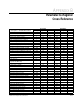
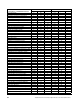
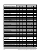
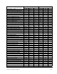
Table A.2 – Register Map Summary
Reg
Description or GV3000 Parameter
Drop_1 Drop_2 Drop_3 (Vector) Drop_3 (V/Hz)
0 Status word 1 Vector torque reference
Torque Reference Source (U.000) (bits 0 to 7)
OCL Feedback Select (U.040) (bits 8 to 15)
Motor Nameplate Volts (H.000)
1 Speed ref value Vector torque feedback Encoder PPR (U.001) Motor Nameplate Base Frequency (H.001)
2 Speed ref sum Reserved Motor Poles (U.002) Motor Nameplate Amps (H.002)
3 Speed feedback Network Out Reg Sources (P.066, P.067) Motor Nameplate Base Frequency (U.003) Torque Boost Voltage (H.003)
4 Terminal strip analog input value Network Out Reg Source (P.068, P.069) Motor Nameplate Amps (U.004) Slip Compensation (H.004)
5 Output speed/frequency Terminal Strip Analog Input Offset (P.009) Motor Nameplate RPM (U.005) DC Braking Enable (H.005)
6 Output voltage Terminal Strip Analog Input Gain (P.010) Magnetizing Current (U.006) DC Braking Start Frequency (H.006)
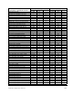
7 Output current
Terminal Strip Analog Input Configure (P.011)
Motor Nameplate Volts (U.007) DC Braking Current (H.007)
8
Network output register 1
Terminal Strip Analog Output Source (P.012)
Torque Self-Tune Result (U.009) DC Braking Time (H.008)
9 Network output register 2 Output Relay Configuration (P.013) Reserved Avoidance Frequency Enable (H.009)
10 Network output register 3 Trim Reference Source (P.014)
Torque Regulator Proportional Gain (U.014)
Avoidance Frequency Midpoint 1 (H.010)
11 Network output register 4 S-Curve Enable (P.019) Torque Regulator Integral Gain (U.015) Avoidance Frequency Band 1 (H.011)
12 Drive fault latch bits — word 1 Jog Speed Reference (P.020) Field Weakening Start RPM (U.016) Avoidance Frequency Midpoint 2 (H.012)
13 Drive fault latch bits — word 2 Jog Ramp Accel Time (P.021) Motor Top Speed (U.017) Avoidance Frequency Band 2 (H.013)
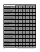
14 # of error log entries (bits 0 to 7)
Parameter processing error flag (bit 8)
Jog Ramp Decel Time (P.022) AC Line Volts (U.018) Avoidance Frequency Midpoint 3 (H.014)
15 Error log entry Stop Type (P.025) Flux Current Regulator Prop. Gain (U.019) Avoidance Frequency Band 3 (H.015)
16 Control Source (P.000) Function Loss Response (P.026)
Flux Current Regulator Integral Gain (U.020)
Sync Direction (H.016)
17 Accel Time 1 (RAMP 1) (P.001) Forward/Reverse Configuration (P.027) Rotor Time Constant (U.021) Power/Snubber Configuration (H.017)
18 Decel Time (RAMP 1) (P.002) Speed Display Scaling (P.028) Motor Nameplate Horsepower (U.022) Volts/Hertz Curve Type (H.018)
19 Minimum Speed (P.003)
Motor Overload Enable (P.040) (bit 0)
Level Sense Start Enable (P.054) (bit 1)
Lo DC Bus Fault Avoid Enable (U.023) (bit2)
Hi DC Bus Fault Avoid Enable (U.024) (bit3)
OCL Proportional Trim Enable (U.048) (bit4)
Zero Speed Hold Time (U.025) Identification Result (H.019)
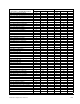
20 Maximum Speed (P.004) Motor Overload Type (P.041) SVC Slip Adjust (U.030) Reserved
21 Current Limit (P.005) Line Dip Ride-Through Time (P.042)
SVC Sync Direction (U.031) (bits 0 to 7)
OCL Lead/Lag Select (U.041) (bits 8 to 15)
AC Line Volts (H.021)
22 Trim Gain Percentage (P.015) Fault Auto Reset Attempts (P.043) SVC Flux Current Regulator Gain (U.032) Overfrequency Limit (H.022)