
User Manual

5-10
AutoMax Network Communication Option Board for the GV3000/SE AC Drive
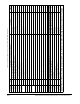
Table 5.5 – Register Assignment for Drop_2 Area Read/Write Registers
Register Bit Description or GV3000/SE Parameter Settings Update
†
32 to 33 Reserved Must be 0
34* 0 to 7 Terminal Strip Analog Output Source (P.012) See drive software instruction manual T
8 to 15 Reserved Must be 0
35 Jog Ramp Accel Time (P.021) 1 = 0.1 seconds T
36 Jog Ramp Decel Time (P.022) 1 = 0.1 seconds T
37 Forward/Reverse Configuration (P.027) See drive software instruction manual T
38 0 Encoder Loss Enable (P.039) 1 = enabled T
1 Output Phase Loss Enable (P.045) 1 = enabled T
2 Manual Reference Preset Enable (P.053) See drive software instruction manual T
3
AUTO/MAN Key Disable (P.052) 1 = key disabled T
4
STOP/RESET Key Disable (P.055) 1 = key disabled T
5 to 15 Reserved Must be 0
39 S-Curve Enable (P.019) 1 = enabled C
40 0 Motor Overload Enable (P.040) 1 = enabled C
1 Level Sense Start Enable (P.054) 1 = enabled C
2 Low DC Bus Fault Avoidance Enable (SVC only) (U.023) 1 = enabled C
3 High DC Bus Fault Avoidance Enable (U.024). Vector only. 1 = enabled C
4 Outer Control Loop Proportional Trim Enable (U.048) 1 = enabled C
5 to 15 Reserved Must be 0
41 Motor Overload Type (P.041) 0 = nC; 1 = FC C
42 Line Dip Ride-Through Time (P.042). V/Hz only. 1 = 0.1 seconds C
43 Fault Auto Reset Attempts (P.043) 0 = disable auto reset C
44 Fault Auto Reset Time (P.044) 1 = 1 second C
45 0 to 7 Network Output Register 1 Source (P.066) Set to 0 for backward compatibility. See
section 3.3.
T
8 to 15 Network Output Register 2 Source (P.067) T
46 0 to 7 Network Output Register 3 Source (P.068) T
8 to 15 Network Output Register 4 Source (P.069) T
*Only the low byte of this register is transferred. The high byte is ignored by the drive.
†
Update Times: 350 ms = 350ms or less. T = 350ms or less when tune/config enable is on. C = 350ms or less when tune/config enable is on
and the drive is stopped.