
User Manual

5-8
AutoMax Network Communication Option Board for the GV3000/SE AC Drive
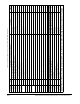
Table 5.4 – Register Assignment for Drop_2 Area Read Only Registers
Register Bit Description or GV3000/SE Parameter Settings Update*
0 Vector torque reference 4095 = 150% torque 5ms
1 Vector torque feedback 4095 = 150% torque 5ms
2 Reserved
3 0 to 7 Network Output Register 1 Source (P.066) 350ms
8 to 15 Network Output Register 2 Source (P.067) 350ms
4 0 to 7 Network Output Register 3 Source (P.068) 350ms
8 to 15 Network Output Register 4 Source (P.069) 350ms
5 Terminal Strip Analog Input Offset (P.009) 350ms
6 Terminal Strip Analog Input Gain (P.010) 1 = 0.001 350ms
7 Terminal Strip Analog Input Configure (P.011) See software manual for settings. 350ms
8 Terminal Strip Analog Output Source (P.012) 350ms
9 Output Relay Configuration (P.013) 350ms
10 Trim Reference Source (P.014) 350ms
11 S-Curve Enable (P.019) 1 = enabled 350ms
12 Jog Speed Reference (P.020) V/Hz: 1 = 0.1 Hz; Vector: 1 = 1 RPM 350ms
13 Jog Ramp Accel Time (P.021) 1 = 0.1 seconds 350ms
14 Jog Ramp Decel Time (P.022) 1 = 0.1 seconds 350ms
15 0 to 7 Stop Type (P.025) 0 = coast; 1 = ramp 350ms
8 to 15 Reserved 350ms
16 Function Loss Response (P.026) 350ms
17 Forward/Reverse Configuration (P.027) See drive software instruction manual 350ms
18 Speed Display Scaling (P.028). Affects front-panel RPM display value reflected in
Drop_1, register 5 (master read).
350ms
*Update Times: 5 ms = 5 ms. 350 ms = 350ms or less.