
User Manual

5-6
AutoMax Network Communication Option Board for the GV3000/SE AC Drive
43 Terminal Strip Analog Input Gain (P.010) 1 = 0.001 T
44 Terminal Strip Analog Input Configure (P.011) See software manual for settings. T
45 Trim Gain Percentage (P.015) 1 = 0.1% T
46 Draw Gain Percentage (P.016) 1 = 0.1% T
47 Speed Regulator Proportional Gain (U.012). Vector only. 1 = 0.01 T
48 Speed Regulator Integral Gain (U.013). Vector only. 1 = 0.01 T
49 Jog Speed Reference (P.020) V/Hz: 1 = 0.1 Hz; Vector: 1 = 1 RPM T
50* 0 to 7 Stop Type (P.025) 0 = coast; 1 = ramp T
8 to 15 Reserved
51* 0 to 7 Function Loss Response (P.026) 0 = fault; 1 = coast without fault T
8 to 15 Reserved
52 Speed Display Scaling (P.028). Affects front-panel RPM display value reflected in
Drop_1, register 5 (master read).
T
53 Control word
0 P.030, Elapsed Time Meter Reset Reset: transition from 0 to 1 T
1 Network inertia comp register enable (enables use of Drop_1, register 35) 5ms
2 Network speed PI limit control enable (enables use of Drop_1, registers 59 & 60) 5ms
3 to 15 Reserved Must be 0
54 and 55 Reserved Must be 0
56* 0 to 7 Output Relay Configuration (P.013)
0 = fault;1 & 2 = running; 3 = network active
C
8 to 15 Reserved
57* 0 to 7 Trim Reference Source (P.014) C
8 to 15 Reserved
58 0 to 7 Torque Reference Source (U.000). Vector only. C
8 to 15 Outer Control Loop Feedback Select (U.040).Vector only. C
59 Option port speed PI high limit. Vector only. 5ms
60 Option port speed PI low limit. Vector only. 5ms
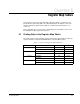
Table 5.3 – Register Assignment for Drop_1 Area Read/Write Registers (Continued)
Register Bit Description or GV3000/SE Parameter Settings Update
†
*Only the low byte (bits 0 to 7) of this register is transferred. The high byte is ignored by the drive.
†
Update Times: 5 ms = 5 ms. 5/0.5: 5ms if speed reference; 0.5 ms if torque reference. 350 ms = 350ms or less. T = 350ms or less when
tune/config enable is on. C = 350ms or less when tune/config enable is on and the drive is stopped.