
User Manual
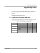

Register Map Tables
5-5
Table 5.3 – Register Assignment for Drop_1 Area Read/Write Registers
Register Bit Description or GV3000/SE Parameter Settings Update
†
32 Sequencing control word 5ms
0Start Run: 0 to 1 transition to start
Jog: 0 = stop; 1 = start
5ms
1Stop 0 = stop; 1 = no stop 5ms
2Fault reset 0 to 1 transition to reset 5ms
3 Run/jog select 1 = jog 5ms
4 Forward/reverse select 1 = reverse 5ms
5 Outer control loop (OCL) enable 5ms
6 Reserved Must be 0 5ms
7 Speed regulation select. Vector only. 0 = torque regulation based on U.000
1 = speed regulation regardless of U.000
5ms
8 Clear error log. Must be maintained for 350ms to assure detection by the drive 0 to 1 transition to clear 350ms
9 to 13 Reserved Must be 0
14 Tune/config input enable 0 = read only control/ref data from
network registers
1 = read all inputs from network registers
T
15 Tune/config update synchronization flag (write) T
33 Option port speed/torque direct reference Vector: 4095=Motor Top Speed (U.017)
V/Hz:4095=Maximum Speed (P.004)
5/0.5
34 Option port trim and OCL direct reference Vector: 4095=Motor Top Speed (U.017)
V/Hz:4095=Maximum Speed (P.004)
5ms
35 Network inertia compensation 5ms
36 Reserved Must be 0
37 Accel Time 1 (RAMP 1) (P.001) 1 = 0.1 seconds T
38 Decel Time (RAMP 1) (P.002) 1 = 0.1 seconds T
39 Minimum Speed (P.003) V/Hz: 1 = 0.1 Hz. Vector: 1 = 1 RPM T
40 Maximum Speed (P.004) V/Hz: 1 = 0.1 Hz. Vector: 1 = 1 RPM T
41 Current Limit (P.005) 1 = 1% T
42 Terminal Strip Analog Input Offset (P.009) T
*Only the low byte (bits 0 to 7) of this register is transferred. The high byte is ignored by the drive.
†
Update Times: 5 ms = 5 ms. 5/0.5: 5ms if speed reference; 0.5 ms if torque reference. 350 ms = 350ms or less. T = 350ms or less when
tune/config enable is on. C = 350ms or less when tune/config enable is on and the drive is stopped.