
User Manual


Installation
2-17
Step 1. Shut Down the Drive
Step 1.1 Disconnect, lock out, and tag all incoming power to the drive.
Step 1.2 Wait five minutes for the DC bus capacitors to discharge.
Step 2. Verify That the DC Bus Capacitors are Discharged
Step 2.1 Use a voltmeter to verify that there is no voltage at the drive’s AC input
power terminals (R/L1, S/L2, T/L3).
Step 2.2 Ensure that the DC bus capacitors are discharged. To check
DC bus potential:
a. Stand on a non-conductive surface and wear insulated gloves.
b. Use a voltmeter to measure the DC bus potential at the DC bus power
terminals shown in figure 2.8.
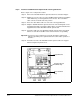
Step 3. Remove the Keypad Bracket from the Drive
Step 3.1 If the drive has:
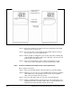
• A Regulator board cover and terminal cover: Remove the three M4
screws from the Regulator board cover. Remove the cover. See
figure 2.9.
• A terminal cover only: If you have this type of drive, this procedure is
easier to perform if you lay the drive on its side. Remove the side cover
from the drive. Use a long magnetized screwdriver to unfasten the four
screws that hold the keypad bracket in.
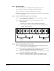
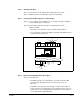
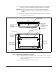
Figure 2.8 – DC Bus Voltage Terminals (30 to 100HP@230VAC and 75 to 200 @ 460VAC Drives)
GND
V (T2)
U (T1)
W (T3)
R
S
T
DC Bus
Volts
P (+)
N (-)