
User Manual

Installation
2-3
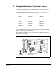
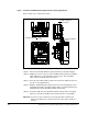
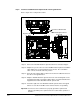
2.1 Setting AutoMax Network Option Board Jumpers
The AutoMax Network option board is shipped with jumpers J4 and J5 connecting
pins 1 and 2 (see figure 2.1).
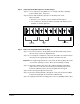
You must change the position of jumpers J4 and J5 to connect pins 2 and 3 before
installing the AutoMax Network option board if your drive is one of these model
numbers:
To check the jumpers, remove the AutoMax Network option board from its anti-static
wrapper. See figure 2.1 for jumper locations.
After changing or checking the jumpers, place the AutoMax Network option board
back in its anti-static wrapper.
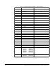
50R41xx 38ER40xx 126ET40xx
50T41xx 38ET40xx 150ER40xx
75R41xx 55ER40xx 150ET40xx
75T41xx 55ET40xx 240ER40xx
125R41xx 85ER40xx 240ET40xx
31ER40xx 85ET40xx 300ER40xx
31ET40xx 126ER40xx 300ET40xx
Figure 2.1 – Jumper Locations on AutoMax Network Option Board
IC23
IC4
IC24
IC19 IC25
IC7
J2
IC26
C4
C5
N2
Z1
XFMR 1
N1
IC22
IC17
IC13
IC12
IC16
Z2
IC2
C69
IC11
IC21
LED1
LED2
D1
C1
IC9
+
J3
IC10
C66
C67
CRY1
IC3
IC20
IC18
IC6
IC5
Z3
C68
C3 D2
IC8
L1
IC1
J4
J5
J1
1
23
J4
J5
1
2
3
J4
J5
Jumpers
J4 and J5
Terminal Connections to
Passive Tap
Ribbon Connector to
Regulator Board