AutoMax Network Communication Option Board for use with GV3000/SE AC Drives M/N 2AX3000 Instruction Manual D2-3308-7
The information in this manual is subject to change without notice. Throughout this manual, the following notes are used to alert you to safety considerations: ! ATTENTION: Identifies information about practices or circumstances that can lead to personal injury or death, property damage, or economic loss. Important: Identifies information that is critical for successful application and understanding of the product.
CONTENTS Contents Chapter 1 Introduction 1.1 AutoMax Network Communication Option Board Description ......................... 1-1 1.2 Where to Find Additional Information .............................................................. 1-1 1.3 Related Hardware and Software ..................................................................... 1-2 1.4 Getting Assistance from Reliance Electric....................................................... 1-2 Chapter 2 Installation 2.
II Appendix A Register Map Summary ........................................................................................... A-1 Appendix B Parameter-to-Register Cross Reference..................................................................
List of Figures Figure 2.1 – Jumper Locations on AutoMax Network Option Board......................... 2-3 Figure 2.2 – DC Bus Voltage Terminals (1 to 5HP @ 460 V) .................................. 2-5 Figure 2.3 – 1 to 5HP @ 460V GV3000/SE Drive ................................................... 2-6 Figure 2.4 – DC Bus Voltage Terminals (7.5 to 10HP) ............................................ 2-9 Figure 2.5 – 7.5 to 10HP @ 460V GV3000/SE Drive ............................................ 2-10 Figure 2.
List of Tables Table 1.1 – Hardware and Software Used with AutoMax Network Option Board (Purchased Separately) ....................................................................... 1-2 Table 2.1 – Locating the Appropriate Installation Procedure.................................... 2-1 Table 2.2 – Model Numbers for 1 to 5HP@460VAC Drives.................................... 2-4 Table 2.3 – Model Numbers for 1 to 20HP@230VAC Drives ................................ 2-12 Table 2.
CHAPTER 1 Introduction This manual describes the AutoMax™ Network Communication Option board (M/N 2AX3000). This board allows a GV3000/SE™ drive to be operated and monitored over the AutoMax network. For normal operation, the GV3000/SE drive can be completely controlled using the Network Option board. This allows use of only a network interface connection, hardwired emergency stop, and three-phase input and output power wiring.
• GV3000/SE 230 VAC 30-100 HP General Purpose (Volts/Hertz) and Vector Duty Drive Software Start-Up and Reference Manual (D2-3416) • GV3000/SE AC Drive Hardware Reference, Installation, and Troubleshooting 30-100 HP @ 230 VAC (D2-3417) • GV3000/SE AC General Purpose (Volts/Hertz) and Vector Duty Bookshelf Drive Software Start-Up and Reference Manual (D2-3426) • GV3000/SE AC Bookshelf Power Modules Hardware Reference, Installation, and Troubleshooting (D2-3427) • Network Communications Module (J2-3001) •
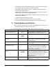
1.4 Getting Assistance from Reliance Electric If you have any questions or problems with the products described in this instruction manual, contact your local Reliance Electric sales office. For technical assistance, call 1-800-726-8112.
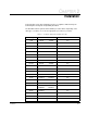
CHAPTER 2 Installation Contact Reliance if the drive installation must be in compliance with the European Community Electromagnetic Compatibility Standards. The AutoMax Network option board installation procedure differs depending on the drive type. Use table 2.1 to locate the appropriate procedure for your drive. Table 2.1 – Locating the Appropriate Installation Procedure Rating Installation GV3000/SE Model Number Use the Procedure in Section … 1 HP 1V21xx 1V24xx 2.4 1 HP 1V41xx 1V44xx 2.
Table 2.1 – Locating the Appropriate Installation Procedure (Continued) Rating 2-2 GV3000/SE Model Number Use the Procedure in Section … 50 HP 50R41xx 2.7 50 HP 50T41xx 2.7 50 HP 50V20xx 2.5 50 HP 50V41xx 50V42xx 2.6 60 HP 60G41xx 60G42xx 2.6 60 HP 60V20xx 2.5 75 HP 75R41xx 2.7 75 HP 75T41xx 2.7 75 HP 75V20xx 2.5 75 HP 75V40xx 2.5 100 HP 100V20xx 2.5 100 HP 100V40xx 2.5 125 HP 125R41xx 2.7 125 HP 125V40xx 2.5 150 HP 150V40xx 2.5 200 HP 200V40xx 2.
2.1 Setting AutoMax Network Option Board Jumpers The AutoMax Network option board is shipped with jumpers J4 and J5 connecting pins 1 and 2 (see figure 2.1).
2.2 Installing the AutoMax Network Option Board in 1 to 5HP@460VAC Drives ! ATTENTION: Only qualified electrical personnel familiar with the construction and operation of this equipment and the hazards involved should install, adjust, operate, or service this equipment. Read and understand this manual and other applicable manuals in their entirety before proceeding. Failure to observe this precaution could result in severe bodily injury or loss of life.
Step 2. Verify That the DC Bus Capacitors are Discharged Step 2.1 Use a voltmeter to verify that there is no voltage at the drive’s AC input power terminals (R/L1, S/L2, T/L3). Step 2.2 Ensure that the DC bus capacitors are discharged. To check DC bus potential: a. Stand on a non-conductive surface and wear insulated gloves. b. Use a voltmeter to measure the DC bus potential at the DC bus power terminals as shown in figure 2.2.
Step 4. Install the AutoMax Network Option Board in the Keypad Bracket Refer to figure 2.3 for component locations. Top View AutoMax Network Option Board Regulator Board Current Feedback Board Front View Side View Figure 2.3 – 1 to 5HP @ 460V GV3000/SE Drive Step 4.1 Remove the AutoMax Network option board from its anti-static wrapper. Step 4.2 Align the key on the connector of the AutoMax Network option board ribbon cable with the key on the Regulator board connector.
Step 4.6 Fasten the left side of the AutoMax Network option board to the keypad bracket using the two plastic rivets. Step 5. Reinstall the Keypad Bracket in the Drive Step 5.1 Reconnect the internal fan assembly power connector (CONN7) to the drive. Align the key on the connector with the slot in the receptacle. Press the connector into position. ! ATTENTION: Proper alignment of the Current Feedback board is critical.
2.3 Installing the AutoMax Network Option Board in 7.5 to 10HP@460VAC Drives ! ATTENTION: Only qualified electrical personnel familiar with the construction and operation of this equipment and the hazards involved should install, adjust, operate, or service this equipment. Read and understand this manual and other applicable manuals in their entirety before proceeding. Failure to observe this precaution could result in severe bodily injury or loss of life.
Step 2. Verify That the DC Bus Capacitors are Discharged Step 2.1 Use a voltmeter to verify that there is no voltage at the drive’s AC input power terminals (R/L1, S/L2, T/L3). Step 2.2 Ensure that the DC bus capacitors are discharged. To check DC bus potential: a. Stand on a non-conductive surface and wear insulated gloves. b. Use a voltmeter to measure the DC bus potential at the DC bus power terminals shown in figure 2.4.
Step 4. Install the AutoMax Network Option Board in the Keypad Bracket Refer to figure 2.5 for component locations. Top View Current Feedback Board Regulator Board Front View Network Option Board Side View Figure 2.5 – 7.5 to 10HP @ 460V GV3000/SE Drive Step 4.1 Remove the AutoMax Network option board from its anti-static wrapper. Step 4.2 Align the key on the connector of the AutoMax Network option board ribbon cable with the key on the Regulator board connector.
Step 4.6 Fasten the left side of the AutoMax Network option board to the keypad bracket using the two plastic rivets. Step 4.7 Reconnect the keypad bracket to the keypad support bracket by inserting the mounting tabs into the slots in the support bracket and tightening the thumb screw. Step 4.8 Align the Regulator board’s 26-conductor ribbon cable connector with the Current Feedback board connector. Press it in until it locks into position. Step 5. Reinstall the Keypad Support Bracket in the Drive Step 5.
2.4 Installing the AutoMax Network Option Board in 1 to 20HP@230VAC Drives ! ATTENTION: Only qualified electrical personnel familiar with the construction and operation of this equipment and the hazards involved should install, adjust, operate, or service this equipment. Read and understand this manual and other applicable manuals in their entirety before proceeding. Failure to observe this precaution could result in severe bodily injury or loss of life.
Step 1. Shut Down the Drive Step 1.1 Disconnect, lock out, and tag all incoming power to the drive. Step 1.2 Wait five minutes for the DC bus capacitors to discharge. Step 1.3 Remove the cover by loosening the four cover screws. Important: Read and understand the warning labels on the inside of the drive before proceeding. Step 2. Verify That the DC Bus Capacitors are Discharged Step 2.1 Use a voltmeter to verify that there is no voltage at the drive’s AC input power terminals (R/L1, S/L2, T/L3). Step 2.
Step 4. Install the AutoMax Network Option Board in the Keypad Bracket Refer to figure 2.7 for component locations. Step 4.1 Remove the AutoMax Network option board from its anti-static wrapper. Step 4.2 Align the key on the connector of the AutoMax Network option board ribbon cable with the key on the Regulator board connector. Press the ribbon cable connector in until it locks into position. Step 4.3 Route the other ribbon cable out of the side of the keypad bracket. Step 4.
Step 5. Reinstall the Keypad Bracket in the Drive Step 5.1 Place the keypad support bracket back into position. Use a magnetic screwdriver to fasten it to the heatsink with the screws removed earlier. Step 5.2 Realign the 26-conductor ribbon cable connector with the connector inside the slot in the keypad support bracket. Carefully press the ribbon cable connector in until the retaining clips lock into place. Step 5.3 Route the Network Drop Cable through the left-most opening at the bottom of the drive.
2.5 Installing the AutoMax Network Option Board in 30 to 100HP@230VAC and 75 to 200 @ 460VAC Drives ! ATTENTION: Only qualified electrical personnel familiar with the construction and operation of this equipment and the hazards involved should install, adjust, operate, or service this equipment. Read and understand this manual and other applicable manuals in their entirety before proceeding. Failure to observe this precaution could result in severe bodily injury or loss of life.
Step 1. Shut Down the Drive Step 1.1 Disconnect, lock out, and tag all incoming power to the drive. Step 1.2 Wait five minutes for the DC bus capacitors to discharge. Step 2. Verify That the DC Bus Capacitors are Discharged Step 2.1 Use a voltmeter to verify that there is no voltage at the drive’s AC input power terminals (R/L1, S/L2, T/L3). Step 2.2 Ensure that the DC bus capacitors are discharged. To check DC bus potential: a. Stand on a non-conductive surface and wear insulated gloves. b.
Figure 2.9 – Location of Terminal Cover and Regulator Board Cover in 30 to 100 HP @ 230 VAC and 75 to 200 HP @ 460 VAC Drives Step 3.2 Remove the terminal cover, which is below the keypad and fastened with two M4 screws. See figure 2.9. Step 3.3 Record connections to the Regulator board terminal strip if they must be disconnected to remove the keypad bracket. Step 3.4 Pull the keypad assembly partly out of the drive.
Step 4.5 Fasten the right side of the AutoMax Network option board to the keypad bracket. Use the two metal M3 screws and lock washers for grounding. Important: You must use the lock washers to properly ground the option board. Improper grounding of the option board can result in erratic operation of the drive. Step 4.6 Fasten the left side of the AutoMax Network option board to the keypad bracket using the two plastic rivets.
Step 5.3 If the drive has: • A Regulator board cover and terminal cover: Replace the Regulator board cover. Fasten it using the three M4 screws removed earlier. • Only a terminal cover: Use a long magnetized screwdriver to fasten the four screws that hold the keypad bracket. Replace the side cover on the drive. Step 5.4 Route the Network Drop Cable through the left-most opening at the bottom of the drive. Step 5.5 Connect the brown wire to terminal 1 of the 2-connector terminal strip.
2.6 Installing the AutoMax Network Option Board in 15 to 25 HP and 25 to 60HP @ 460V Drives ! ATTENTION: Only qualified electrical personnel familiar with the construction and operation of this equipment and the hazards involved should install, adjust, operate, or service this equipment. Read and understand this manual and other applicable manuals in their entirety before proceeding. Failure to observe this precaution could result in severe bodily injury or loss of life.
Important: Read and understand the warning labels on the outside of the drive before proceeding. Step 1. Shut Down the Drive Step 1.1 Disconnect, lock out, and tag all incoming power to the drive. Step 1.2 Wait five minutes for the DC bus capacitors to discharge. Step 1.3 Remove the cover by loosening the four cover screws. Important: Read and understand the warning labels on the inside of the drive before proceeding. Step 2. Verify That the DC Bus Capacitors are Discharged Step 2.
DC Bus Volts Input Wiring Figure 2.12 – DC Bus Voltage Terminals (25 to 60 HP @ 460V) Step 3.3 Disconnect the 26-conductor Regulator board ribbon cable from the Power Supply board (located on the right side below the keypad). You can see the connector through the slot on the keypad support bracket. Use a small screwdriver inserted through the slot to spread the retaining clips on the connector to release it. Step 4. Install the AutoMax Network Option Board in the Keypad Bracket Refer to figure 2.
Top View Top View Network Option Board Regulator Board Network Option Board Regulator Board GRD RPM VO LTS AMPS Hz Kw TORQUE Pa sswo rd RUNNING REMOTE JOG AUTO FO RWARD REVERSE PRO GRAM ENTER RP M STOP RESET V OLT S A MP S Hz Kw T OR QU E P a ssw ord START Front View 16A STOP RESET RUNNING R E M OT E JO G A UT O F OR W A R D RE V E RS E P R OG R A M Front View ENTER STA RT 20A GRD GRD 709579-1 15 to 25 HP @ 460V 25 to 60 HP @ 460V Figure 2.
2.7 Installing the AutoMax Network Option Board in 50 to 100 HP and 100 to 150 HP @ 460V Drives ! ATTENTION: Only qualified electrical personnel familiar with the construction and operation of this equipment and the hazards involved should install, adjust, operate, or service this equipment. Read and understand this manual and other applicable manuals in their entirety before proceeding. Failure to observe this precaution could result in severe bodily injury or loss of life.
Step 2. Verify That the DC Bus Capacitors are Discharged Step 2.1 Use a voltmeter to verify that there is no voltage at the drive’s AC input power terminals (1L1, 1L2, 1L3). Step 2.2 Ensure that the DC bus capacitors are discharged. To check DC bus potential: a. Stand on a non-conductive surface and wear insulated gloves. b. 50 to 100 HP @ 460 V only: Use a voltmeter to measure the DC bus potential at the diode bridge. Refer to figure 2.14. c.
Step 3.4 Use a magnetic screwdriver to remove the four screws and lock washers that fasten the keypad bracket to the hinged mounting panel. Hold the keypad bracket as you remove the screws. Power Module Interface Board Fuses (–) (+) DC Bus Measuring Points Regulator Panel Power Module Interface Board DC bus measuring points are behind the Regulator Panel on the Power Module Interface board. Keypad Regulator Board Power Module Interface Board Figure 2.
Step 4. Install the AutoMax Network Option Board in the Keypad Bracket See figure 2.14 (50 to 100 HP drives) or 2.15 (100 to 150 HP drives) for part locations. Step 4.1 Remove the AutoMax Network option board from its anti-static wrapper. Step 4.2 Align the key on the connector of the AutoMax Network option board ribbon cable with the key on the Regulator board connector. Press the ribbon cable connector in until it locks into position. Step 4.
2.8 Installing the AutoMax Network Option Board in 200 to 400HP@460VAC Drives ! ATTENTION: Only qualified electrical personnel familiar with the construction and operation of this equipment and the hazards involved should install, adjust, operate, or service this equipment. Read and understand this manual and other applicable manuals in their entirety before proceeding. Failure to observe this precaution could result in severe bodily injury or loss of life.
Step 2.5 Ensure that the DC bus capacitors are discharged. To check DC bus potential: a. Stand on a non-conductive surface and wear insulated gloves. (600 V) b. Use a voltmeter to check the DC bus potential at the Voltmeter Test Points on the Power Module Interface board. See figure 2.16. Step 3. Remove the Keypad Bracket from the Drive Refer to figure 2.16 for component locations.
Step 4.3 Fasten the board to the drive with four 732 ⁄ ″ nuts. Metal nuts must be used for proper grounding of the AutoMax Network option board. Step 4.4 Connect the brown wire to terminal 1 of the 2-connector terminal strip. Connect the white wire to terminal 2. Step 4.5 Align the key on the connector of the AutoMax Network option board ribbon cable with the key on the Regulator board connector. Press the ribbon cable connector in until it locks into position. Step 4.
2.9 Installing the AutoMax Network Option Board in 2 to 15 Amp and 24 to 30 Amp GV3000/SE Bookshelf Drives ! ATTENTION: Only qualified electrical personnel familiar with the construction and operation of this equipment and the hazards involved should install, adjust, operate, or service this equipment. Read and understand this manual and other applicable manuals in their entirety before proceeding. Failure to observe this precaution could result in severe bodily injury or loss of life.
Unless otherwise indicated, keep all hardware that is removed. You will need it for reassembly. This includes screws, lock washers, and rivets. Important: Read and understand the warning labels on the outside of the drive before proceeding. Step 1. Shut Down the Drive Step 1.1 Disconnect, lock out, and tag all incoming power to the drive. Step 1.2 Wait five minutes for the DC bus capacitors to discharge. Step 1.3 Disconnect all faceplate wiring. Step 1.
Cover Screw Breakout Panel AC Input Power Terminals (L1, L2, L3) DC Bus Measuring Point (–)45, (+)47 Figure 2.
Cover Screw Front Panel Screws Breakout Panel Figure 2.
Keypad/Display Cable Connector Regulator Board Regulator Board Ribbon Cable AC Input Power Terminals (L1, L2, L3) DC Bus Measuring Point (–)45, (+)47 Figure 2.19 – 24 to 30 Amp GV3000/SE Bookshelf Drive (Cover and Front Panel Removed) ! Step 3. ATTENTION: The drive contains printed circuit boards that are static-sensitive. An anti-static wrist band should be worn by any person who touches the drive’s components, connectors, or wiring.
Keypad/Display Cable Connector Regulator Board Regulator Board Ribbon Cable AutoMax Network Option Board Figure 2.20 – Installing the AutoMax Network Option Board in GV3000/SE Bookshelf Drive Step 4. Reattach the Cover Step 4.1 Remove enough tabs on the faceplate breakout panel to allow the Network Drop Cable through. Step 4.2 Route the Network Drop Cable through the breakout panel. Step 4.3 Reconnect the keypad/display cable to the cover.
2.10 Connecting the GV3000/SE Drive to an AutoMax Network ATTENTION: AutoMax networks with more than 5 drops might produce communication errors if 10-foot drop cables are used. Wherever possible, 30-inch drop cables or, if necessary, 5-foot drop cables should be used. Failure to observe this precaution could result in damage to, or destruction of, equipment. ! See figure 2.21 for cabling and termination connections.
CHAPTER 3 Drive Configuration This section describes how to configure a GV3000/SE drive for use with an AutoMax network. When the Network Connection Type (P.061) parameter is configured for basic drive connection (P.061=0), the GV3000/SE drive occupies a single network drop. This first drop image is referred to as Drop_1 in this manual. The actual drop number is configured using the Network Drop Number (P.060) parameter. When P.061 is configured for full drive connection (P.
3.2 Drive Response to Loss of Network Communication The Network Option board attempts to remain active on the AutoMax network at all times, regardless of the control source setting. At power up, the drive delays for approximately 20 seconds before indicating a loss of network communication. If communication is interrupted: Step 1. The Network Option board immediately notifies the drive regulator. Step 2. The Network Option board attempts to re-establish communication with the network master. Step 3.
P.061 Network Connection Type This parameter selects one of two AutoMax network connection types. Parameter Range: 0 = Basic drive connection 1 = Full drive connection Default Setting: 0 Parameter Type: Configurable Refer also to parameters: N/A Setting P.061 = 0 provides basic drive control from the AutoMax network. Only essential drive data (reference, sequencing, basic tuning, and feedback data) are transferred over the network. This allows a higher density network with moderate functionality.
P.062 Option Port: Communication Loss Response This parameter specifies how the drive responds to a network communication loss when the Control Source (P.000) parameter is set to OP (Option port). Parameter Range: 0 = IET fault 1 = Hold last reference 2 = Use terminal strip reference Default Setting: 0 Parameter Type: Tunable Refer also to parameters: P.
P.062 Option Port: Communication Loss Response (continued) If P.062 = 1 The drive continues to operate, using the last reference received from the network master. ! ATTENTION: In volts/hertz regulation, if P.000 (Control Source) is set to OP (Option Port), and P.062 is set to 1 (hold last reference), and the drive loses communication with the network, the drive will maintain the last frequency command sent to it.
P.062 Option Port: Communication Loss Response (continued) If P.062 = 2 The drive gets its speed/torque reference from the terminal strip analog input and its stop input from the terminal strip stop input. All other inputs are held at the last values received from the network master. This allows the network master to continue controlling the drive reference with a direct-wired analog output to input, and to stop the drive with a direct-wired digital output to input. Note that if P.
P.063 Option Port: Network Reference Source This parameter specifies where the drive gets its speed or torque reference when the option port is selected as the control source (P.000 = OP). Parameter Range: 0 = Direct reference 1 to 8 = Broadcast Default Setting: 0 Parameter Type: Configurable Refer also to parameters: U.000 Torque Reference Source Speed or torque control is configured by parameter U.000 (Torque Reference Source) and by specifying TRQ/SPD in P.
P.064 Option Port: Network Trim Reference Source This parameter specifies where the drive gets its trim reference when the option port is selected as the control source (P.000 = OP). Parameter Range: 0 = Direct trim reference register 1 to 8 = Broadcast register 1 to 8, respectively Default Setting: 0 Parameter Type: Configurable Refer also to parameters: P.063 Option Port: Network Reference Source U.
P.066 to P.069 Network Output Register 1 Source through Network Output Register 4 Source These parameters select the signal written to the option port network output registers 1 through 4. Parameter Range: 0 = (P.066) Motor Kw display value (P.067) Motor torque display value (P.068) Output power factor (P.
P.066 to P.069 Network Output Register 1 Source through Network Output Register 4 Source (continued) P.066 0 = Motor KW display value . . . 12 P.067 0 = Motor torque display value . . . 12 Network Module Network Output Register 1 P.068 Network Output Register 2 0 = Output power factor . . . 12 Network Output Register 3 Network Output Register 4 P.069 0 = Encoder counter (x 4) . . . 12 Figure 3.
CHAPTER 4 Programming This section describes the organization of data in the AutoMax Network Option Board and how the network accesses the data. 4.1 The Network and Other Control Sources You can use the front panel keypad/display to change parameter values when the Control Source parameter (P.000) is set to 2 (OP). However, if the tune/config input enable bit (Drop_1, register 32, bit 14) is on, any changes made through the keypad might be overwritten when the next network update occurs. 4.
Output data is one of two types: • Runtime Signal: This is data such as the selected speed reference value, drive status (such as ready or running), drive fault flags, the state of terminal strip digital inputs, and motor status values (RPM, VOLTS, AMPS). This information is transferred every speed loop scan period (5ms). • Tunable, Configurable, and Status: All other information provided by the drive. This typically includes all stored drive parameter values.
If you only want to transfer control/reference data, leave the tune/config input enable bit at 0 (off). This forces you to configure the drive through another control source, such as the front panel keypad/display or CS3000 software, but allows you to control the drive (run, jog, stop, reset, and the reference) from the network master. 4.3.1 Tune/Config Update Synchronization Flag This flag allows the network master application program to track when the drive has updated tunable and configurable inputs.
Alternative Synchronization Methods The tune/config update synchronization flag applies only to Drop_1. To determine if the drive received data written to other drops, you must use other methods. Some alternate methods are: • Program a delay after writing to the network master’s memory. If you know the number of drops on the network, and 350ms is added for processing time at the drive end, this time is predictable.
4.6 Drive Ready Status Bit The Drive Ready status bit (Drop_1, register 0, bit 0) indicates that a 0-to-1 transition on the start input will start the drive.
Update times assume communication is active. Outputs are transferred whenever communication is active. Inputs are only transferred when communication is active and P.000 is set to 2 (OP). See section 4.3 for information on setting up transferrable data types. 4.9 GV3000/SE Drive Parameters Not Accessible Over the Network The following GV3000/SE drive parameters are not accessible over the AutoMax network at any time. P.006, Second Menu Password P.007, Terminal Strip Digital Inputs Configure P.
CHAPTER 5 Register Map Tables This section presents the register map tables. Brief descriptions of parameters are provided in the register map tables. For detailed parameter descriptions, refer to the software manual. For parameter descriptions of network-specific parameters, see section 3.3. These map tables are for version 6.03 of the Regulator board. Earlier versions of the board might have different parameter options. 5.
5-2 AutoMax Network Communication Option Board for the GV3000/SE AC Drive Description or GV3000/SE Parameter Terminal strip digital input 1 (start) Terminal strip digital input 2 (stop) Terminal strip digital input 3 (fault reset) Terminal strip digital input 4 (run/jog select) 8 9 10 11 Speed feedback Terminal strip analog input value (conditioned with offset, gain, and inversion) Output speed/frequency (front panel RPM display) Output voltage (front panel VOLTS display) Output current (fron
Register Map Tables 5-3 Self-tuning status (SF). Vector only. Overspeed (OSP). Vector only.
5-4 AutoMax Network Communication Option Board for the GV3000/SE AC Drive 0 to 7 Error log entry (second most recent error) Option Port: Communication Loss Response (P.062) Option Port: Network Reference Source (P.063) 29 30 *Update Times: 5 ms = 5 ms. 350 ms = 350ms or less. Software Version Number (P.098) 8 to 15 Option Port: Network Trim Reference Source (P.064) Network Connection Type (P.061) 28 0 to 7 Elapsed Time Meter (P.029) 27 601 = Version 6.
Register Map Tables 5-5 Description or GV3000/SE Parameter Reserved Speed regulation select. Vector only. Clear error log. Must be maintained for 350ms to assure detection by the drive 6 7 8 Decel Time (RAMP 1) (P.002) Minimum Speed (P.003) Maximum Speed (P.004) Current Limit (P.005) Terminal Strip Analog Input Offset (P.009) 38 39 40 41 42 1 = 1% V/Hz: 1 = 0.1 Hz. Vector: 1 = 1 RPM V/Hz: 1 = 0.1 Hz. Vector: 1 = 1 RPM 1 = 0.1 seconds 1 = 0.
5-6 AutoMax Network Communication Option Board for the GV3000/SE AC Drive Draw Gain Percentage (P.016) Speed Regulator Proportional Gain (U.012). Vector only. Speed Regulator Integral Gain (U.013). Vector only. Jog Speed Reference (P.020) Stop Type (P.025) 46 47 48 49 50* Function Loss Response (P.026) Output Relay Configuration (P.013) Trim Reference Source (P.014) 5ms Times: 5 ms = 5 ms. 5/0.5: 5ms if speed reference; 0.5 ms if torque reference. 350 ms = 350ms or less.
Register Map Tables 5-7 Network Connection Type (P.061) Option Port: Communication Loss Response (P.062) Option Port: Network Reference Source (P.063) 8 to 15 Option Port: Network Trim Reference Source (P.064) 0 to 7 8 to 15 Reserved 0 to 7 Description or GV3000/SE Parameter 0 = direct; 1 to 8 = broadcast 1 to 8 0 = direct; 1 to 8 = broadcast 1 to 8 0 = basic; 1 = full Settings C C T C Update† Times: 5 ms = 5 ms. 5/0.5: 5ms if speed reference; 0.5 ms if torque reference.
5-8 AutoMax Network Communication Option Board for the GV3000/SE AC Drive Speed Display Scaling (P.028). Affects front-panel RPM display value reflected in Drop_1, register 5 (master read). *Update Times: 5 ms = 5 ms. 350 ms = 350ms or less. Forward/Reverse Configuration (P.027) Reserved 8 to 15 18 Stop Type (P.025) 15 17 Jog Ramp Decel Time (P.022) 0 to 7 14 Function Loss Response (P.026) Jog Ramp Accel Time (P.021) 13 16 Jog Speed Reference (P.020) 12 Output Relay Configuration (P.
Register Map Tables 5-9 Low DC Bus Fault Avoidance Enable (SVC only) (U.023) High DC Bus Fault Avoidance Enable (U.024). Vector only. Outer Control Loop Proportional Trim Enable (U.048) 2 3 4 Carrier Frequency (kHz) (P.047) Volts/Hertz or Vector Regulation (P.048) Country Defaults (P.049) Inertia Compensation Gain (U.027). Vector only. Losses Compensation Gain (U.028). Vector only. Option Port: Type and Version (P.065) 26 27 28 29 30 31 *Update Times: 5 ms = 5 ms. 350 ms = 350ms or less.
5-10 AutoMax Network Communication Option Board for the GV3000/SE AC Drive Output Phase Loss Enable (P.045) Manual Reference Preset Enable (P.053) AUTO/MAN 1 2 3 Low DC Bus Fault Avoidance Enable (SVC only) (U.023) High DC Bus Fault Avoidance Enable (U.024). Vector only. Outer Control Loop Proportional Trim Enable (U.048) 2 3 4 Network Output Register 4 Source (P.069) 8 to 15 Set to 0 for backward compatibility. See section 3.3. 1 = 1 second 0 = disable auto reset 1 = 0.
Register Map Tables 5-11 Country Defaults (P.049) Reserved 0 to 7 8 to 15 49* and the drive is stopped. *Only the low byte of this register is transferred. The high byte is ignored by the drive. †Update Times: 350 ms = 350ms or less. T = 350ms or less when Reserved Reserved 48 Carrier Frequency (kHz) (P.047) 0 to 7 8 to 15 47* 0 = USA; 1 = EUr; 2 = JPn Must be 0 0 = 2kHz; 1 = 4kHz; 2 = 8kHz Settings C C Update† tune/config enable is on.
5-12 AutoMax Network Communication Option Board for the GV3000/SE AC Drive Rotor Time Constant (U.021) Motor Nameplate Horsepower (U.022) Zero Speed Hold Time (U.025) SVC Slip Adjust (U.030) SVC Sync Direction (U.031) Outer Control Loop Lead/Lag Select (U.041) 0 to 7 8 to 15 17 18 19 20 21 *Update Times: 350 ms = 350ms or less. Outer Control Loop Reference Gain (U.044) Flux Current Regulator Integral Gain (U.020) 16 25 Flux Current Regulator Proportional Gain (U.
Register Map Tables 5-13 Drive panel amps Drive panel volts Outer Control Loop Trim Range Percentage (U.047) Power Module Type (P.099) 28 29 30 31 Motor Nameplate Base Frequency (U.003) Motor Nameplate Amps (U.004) Motor Nameplate RPM (U.005) Magnetizing Current (U.006) Motor Nameplate Volts (U.007) Torque Regulator Proportional Gain (U.014) Torque Regulator Integral Gain (U.015) Field Weakening Start RPM (U.016) Motor Top Speed (U.017) AC Line Volts (U.
5-14 AutoMax Network Communication Option Board for the GV3000/SE AC Drive Outer Control Loop Proportional Gain (U.045) Outer Control Loop Integral Gain (U.046) Outer Control Loop Trim Range Percentage (U.047) Reserved 60 61 62 63 Must be 0 1 = 0.001 1 = 0.01 1 = 0.01 1 = 0.001 1=1 1 = 0.01 rad/s Must be 0 1 = 1 rad/s 0 = bypass; 1 = lead/lag; 2 = lag/lead See drive software instruction manual 1 = 0.01 Must be 0 1 = 0.001 1 = 0.001 1 = 0.001 1 = 0.
Register Map Tables 5-15 Torque Boost Voltage (H.003) Slip Compensation (H.004) DC Braking Enable (H.005) 3 4 5 Avoidance Frequency Enable (H.009) 9 1 = 1 VAC 1 = 0.01% of base frequency 1 = 0.1 Hz Volts/Hertz Curve Type (H.018) Identification Result (H.019) Reserved AC Line Volts (H.021) Overfrequency Limit (H.022) 18 19 20 21 Power Module Type (P.099) 31 *Update Times: 350 ms = 350ms or less. Drive panel volts Reserved 30 Drive panel amps 28 29 Power Module Output Amps (P.
5-16 AutoMax Network Communication Option Board for the GV3000/SE AC Drive Torque Boost Voltage (H.003) Slip Compensation (H.004) DC Braking Enable (H.005) 35 36 37 Avoidance Frequency Enable (H.009) 41 See drive software instruction manual Volts/Hertz Curve Type (H.018) Must be 0 1 = 0.1 Hz 1 = 1 VAC Must be 0 See drive software instruction manual C C C C C T T T T T T T T T T T T T T T T Update* *Update Times: T=350ms or less when tune/config enable is on.
APPENDIX A Register Map Summary Table A.1 – Key to Table A.
A-2 AutoMax Network Communication Option Board for the GV3000/SE AC Drive Status word 1 Speed ref value Speed ref sum Speed feedback Terminal strip analog input value Output speed/frequency Output voltage Output current Network output register 1 Network output register 2 Network output register 3 Network output register 4 Drive fault latch bits — word 1 Drive fault latch bits — word 2 # of error log entries (bits 0 to 7) Parameter processing error flag (bit 8) Error log entry Control Sourc
Register Map Summary A-3 Encoder Loss Enable (P.039) (bit 0) Output Phase Loss Enable (P.045) (bit 1) Manual Ref. Preset Enable (P.053) (bit2) AUTO/MAN Key Disable (P.052) (bit 3) STOP/RESET Key Disable (P.055) (bit 4) S-Curve Enable (P.019) (bit 4) Motor Overload Enable (P.040) (bit 0) Level Sense Start Enable (P.054) (bit 1) Lo DC Bus Fault Avoid. Enable (U.023) (bit 2) Hi DC Bus Fault Avoid. Enable (U.024) (bit 3) OCL Proportional Trim Enable (U.048) (bit 4) Motor Overload Type (P.
A-4 AutoMax Network Communication Option Board for the GV3000/SE AC Drive Speed Reg. Proportional Gain (U.012) Speed Regulator Integral Gain (U.013) Jog Speed Reference (P.020) Stop Type (P.025) Function Loss Response (P.026) 47 48 49 50 51 Reserved Reserved Elapsed Time Meter Reset (P.030) (bit0) Network inertia comp enable (bit 1) Network speed PI limit control en (bit2) Reserved Reserved Output Relay Configuration (P.013) Trim Reference Source (P.014) Torque Ref. Source (U.
APPENDIX B Parameter-to-Register Cross Reference Description or GV3000/SE Parameter AC Line Volts (H.021) AC Line Volts (U.018) Accel Time 1 (RAMP 1) (P.001) Analog input signal loss (AIn) Asymmetrical bus charge (UbS) Auto or manual reference selected AUTO/MAN Key Disable (P.052) Avoidance Frequency Band 1 (H.011) Avoidance Frequency Band 2 (H.013) Avoidance Frequency Band 3 (H.015) Avoidance Frequency Enable (H.009) Avoidance Frequency Midpoint 1 (H.010) Avoidance Frequency Midpoint 2 (H.
Description or GV3000/SE Parameter Drive panel amps Drive panel volts Drive power electronic overload (PUo) Drive ready Drive running Earth current failure (ground fault) (EC) EEr EL Elapsed Time Meter (P.029) Electronic thermal overload (OL) Encoder loss (EL) Encoder Loss Enable (P.039) Encoder PPR (U.001) Error log clear Error log entry (most recent error) Error log entry (second most recent) Fatal system error Fault active Fault Auto Reset Attempts (P.043) Fault Auto Reset Time (P.
Description or GV3000/SE Parameter H.021, AC Line Volts H.022, Overfrequency Limit HId (high time identification aborted) High DC Bus Fault Avoid. Enable (U.024) High DC bus voltage (HU) High line voltage (HIL) High time identification aborted (HID) Identification request not performed (nld) Identification Result (H.019) Inertia Compensation Gain (U.027) Input phase loss (IPL) Input Power/Snubber Config. (H.017) IPL (input phase loss) Jog Ramp Accel Time (P.021) Jog Ramp Decel Time (P.
Description or GV3000/SE Parameter Network speed PI limit control enable nld (Identification request not performed) Number of error log entries NVRAM write failure (EEr) OC (overcurrent, steady state) OCA (overcurrent, at acceleration) OCb (overcurrent, at DC braking) OCd (overcurrent, at deceleration) OF (overfrequency) OH (drive overtemperature) OL (electronic thermal overload) OPL (motor output phase loss) Option port speed PI high limit Option port speed PI low limit Option port speed/torque direct ref
Description or GV3000/SE Parameter P.006, Second Menu Password P.007, Term Strip Digital Inputs Configure P.008, Term Strip Speed Reference Source P.009, Terminal Strip Analog Input Offset P.010, Terminal Strip Analog Input Gain P.011, Term Strip Analog Input Configure P.012, Term Strip Analog Output Source P.013, Output Relay Configuration P.014, Trim Reference Source P.015, Trim Gain Percentage P.016, Draw Gain Percentage P.017, Accel Time 2 (RAMP 2) P.018, Decel Time 2 (RAMP 2) P.019, S-Curve Enable P.
Description or GV3000/SE Parameter P.062, Option Port: Comm Loss Response P.063, Option Port: Network Ref Source P.064, Option Port: Netw Trim Ref Source P.065, Option Port: Type and Version P.066, Network Output Register 1 Source P.067, Network Output Register 2 Source P.068, Network Output Register 3 Source P.069, Network Output Register 4 Source P.090, Diagnostics Source P.091, Diagnostics Display P.095, Power Module Output Amps P.098, Software Version Number P.
Description or GV3000/SE Parameter Sync Direction (H.016) Terminal Strip Analog Input Config (P.011) Terminal Strip Analog Input Gain (P.010) Terminal Strip Analog Input Offset (P.009) Terminal strip analog input value Terminal Strip Analog Output Source (P.
Description or GV3000/SE Parameter U.028, Losses Compensation Gain U.030, SVC Slip Adjust U.031, SVC Sync Direction U.032, SVC Flux Current Regulator Gain U.040, OCL Feedback Select U.041, OCL Lead/Lag Select U.042, OCL Lead/Lag Low Frequency U.043, OCL Lead/Lag Ratio U.044, OCL Reference Gain U.045, OCL Proportional Gain U.046, OCL Integral Gain U.047, OCL Trim Range Percentage U.
INDEX 75 ohm terminating load, 1-2 D A DeviceNet Network Communication Option Board, 3-2 direct reference, 3-7 trim reference, 3-8 drive configuration, 3-1 connecting to AutoMax network, 2-38 power-up, 3-2 ready status bit, 4-5 response to network communication loss, 3-2, 3-4 drop cable, installing, 2-38 drop number, 3-2 Drop_1 read only registers, 5-2 read/write registers, 5-5 Drop_2 read only registers, 5-8 read/write registers, 5-10 Drop_3, 4-5 vector read only registers, 5-12 read/write registers, 5-
G GV3000/SE drive, connecting to network, 2-38 Network Output Register 1 Source (P.066), 3-9 Network Output Register 2 Source (P.067), 3-9 Network Output Register 3 Source (P.068), 3-9 Network Output Register 4 Source (P.
read/write registers, 4-5 Drop_1, 5-5 Drop_2, 5-10 Drop_3 (vector), 5-13 Drop_3 (volts/hertz), 5-16 reference source, network, 3-7 trim, network source, 3-8 register map summary, A-1 map tables, 5-1 maps, 4-5 parameter cross reference, B-1 related hardware and software, 1-2 ReSource™ Interface Cable, 1-2 runtime signal data, 4-2 S start input, timing, 4-4 synchronization alternatives, 4-4 flag, 4-3 T technical assistance, 1-2 terminating load, 1-2 installing, 2-38 Index timing requirements, 4-4 transfer
U.S. Drives Technical Support Tel: (1) 262.512.8176, Fax: (1) 262.512.2222, Email: support@drives.ra.rockwell.com, Online: www.ab.com/support/abdrives Publication D2-3308-7– February 1999 Copyright © 1999 Rockwell Automation, Inc. All Rights Reserved.