
User Manual
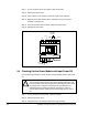
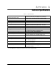


30-100 HP GV3000/SE System Wiring Diagram
APPENDIX B
30-100 HP GV3000/SE System Wiring Diagram
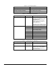
Power Supply
24 VDC
24 VDC Common
+15 VDC
–15 VDC
+5 VDC
Regulator Common
Isolated +15 VDC
Isolated Common
Gate Power
DC
Bus
Pre-Charge
Control
CN12
CN20
CN11
CN21
CN19 CN13 CN14 CN15 CN16 CN17 CN18
U1
V1
W1 U2 V2
W2
12 12 12 12 12 12 12 12
Bus Voltage
Circuit
Gate Circuit &
Dead Band
Circuit
Gate Signals
Bus Voltage Feedback
Regulator Power Supply
Gate Power Supply
CN7
CN8
CN6
CN5
CN4
CN3
CN2
CN1
CN9
CN10
Phase U/W Bus Sensor
Phase V Current Feedback
Phase U Current Feedback
Heatsink
Overheat
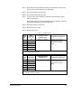
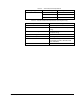
Red
Black
Yellow
AWG #24
T
Red
Black
Yellow
AWG #24
T
Red
Black
Yellow
AWG #24
T
Red
Black
Yellow
AWG #26
T
Red
Black
Yellow
AWG #26
T
T
1
2
3
1
2
3
1
2
3
1
2
3
1
2
3
1
2
3
1
2
3
1
2
3
Fan 1
40D
Fan 2
180D
Fan 3
180D
Fan 4
80D
Fan 5
80D
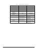
CN9
CN10
+ +
+
+ +
1
2
3
4
1
2
3
4
T
1 234
1
234
CT2
CT1
Current
Feedback
Circuit
CT5
7 >
G3
G1
E1
W1
G2
W2
E2
G1
E1
G2
E2
G1
E1
G2
E2
G2
V1
V2
G1
U1
U2
TH1
MC-B6002
C1
C2 C3
C4
C5
> 6
4700 µF/400 V
453136B
CT4
G1
E1
G1
E1
G1
E1
G2
E2
G2
E2
G2
E2
P
P
P
1
2
3
4
PR
1
2
1
2
P
LED 1
LED
4 >
FU1
R1
10Ω/120 W
R2
2.0KΩ/40 W
5 >
Fuse
250 A
3 >
DM1
MOV3
MOV1 MOV2
2 >
C9
0.003 µF/500 V
Manual
Disconnect
Fuse AC Reactor
1 >
R/L1
S/L2
T/L3
User-supplied
+
–
DC Bus
DC Bus Common
DC Bus
Volts
For Diode
For Diode
For IGBT
For IGBT
For Power Supply
907020
907020
907017
PISC-40
S-B6027-2
827711
J6
MB-B6010
*
< 8
W/T3
V/T2
U/T1
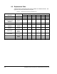
Regulator Power Supply
Bus Voltage Feedback
Phase W Current Feedback
Phase V Current Feedback
Phase U Current Feedback
A/D
Converter
Microprocessor
System
IGBT Gate Signals
Encoder Phase A
Encoder Phase A
Encoder Phase B
Encoder Phase B
+15 VDC
4
5
6
7
8
9
C
C
Encoder Phase A
Encoder Phase B
J17
Analog
Meter Output
Reg. Com.
Current Source
Voltage Source
Dynamic Braking Control
24 VDC
Common
24 VDC Common
10
11
26
27
Meter Output Signal
To optional
Dynamic Braking kit
28
30
31
29
N.O.
N.C.
IET
IET/Controller Running
Relay Contacts
1
2
3
4
5
6
7
8
9
10
J7
+15 VDC
+12 VDC
2
3
5
1
2
3
J8
TXD
TXD
TXD
Reg. Common
Reg. Common
Reg. Common
RXD
RXD
RXD
–15 VDC
DTR
–12 VDC
RS-232 TXD
RS-232 RXD
To Operator
Interface Module
PC Communications
Port (RS-232)
Control Terminal
PC Communications
(RS-232)
12
13
14
15
25
24
23
22
21
20
19
18
17
16
1.87 KΩ
Isolated +15 VDC
Voltage
Current
Analog Speed Ref.
J4
Isolated Common
24 VDC Common
START
STOP
RESET
RUN/JOG
Function Loss
Digital Input 6 (FWD/REV)
Digital Input 7 (RAMP1/RAMP2)
Digital Input 8 (REMOTE/LOCAL)
+24 VDC
Heat Sensor
Local Operator Interface
Display and Indicator LEDs
8.8.8.8.
Regulator Board
0-56921
Ribbon Cable
Membrane Switch
Configurable
Digital Inputs
Digital
Inputs
Speed Reference
Input Wiring
1 >
2 >
3 >
4 >
5 >
6 >
7 >
8 >
Capacity of AC reactor is 84 µH/125 A for 30 HP unit, 66 µH/160 A
for 40 HP and 50 HP units, 54 µH/200 A for 60 HP unit, 42 µH/250 A
for 75 HP unit, and 36 µH/300 A for 100 HP unit.
One 512902 diode bridge is required for 30 HP to 50 HP units,
and six 514706 diode bridges for 60 HP to 100 HP units.
286331 fuse is used for 30 Hp to 50 HP units, and 286325 fuse for
60 HP to 100 HP units.
One 10 Ohms/120 W resistor is used for 30 HP to 50 HP units, and
one 10 Ohms/220 W resistors for 60 HP to 100 HP units.
One 1 KOhm/40 W resistor is used for 30 HP to 50 HPunits, and two
1 KOhm/40 W resistors for 60 to 100 HP units.
Five capacitors are used for 30 HP to 50 HP units, and nine capacitors
for 60 HP to 100 HP units.
Three 536664 IGBT modules are used for 30 HP to 50 HP units,
and three 536174 IGBT modules and three 536175 IGBT modules
for 60 HP to 100 HP units.
Two 907018 diode module fan assemblies are used for 30 HP to
50 HP units, and one 907019 diode module fan assembly is used
for 60 HP through 100 HP units. For 60 HP through 100 HP units,
pins 2 and 3 of CN6 are jumpered.
Note: Fan 2 to Fan 5 are ON/OFF-controlled by temperature (48/41°C).
250 Ω
J9
4
1
2
3
4
B-1