
User Manual

7-7
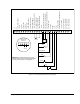
Wiring the Regulator Board Terminal Strip
• Terminal 7: Encoder Phase B Differential Input
• Terminal 8: Encoder Phase B Not Differential Input
• Terminal 9: Encoder/Regulator Common
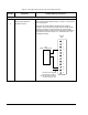
Use the following procedure to connect an encoder to the regulator's terminal strip:
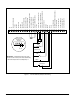
Step 1. Connect the encoder's wires to terminals 4 through 9 of the terminal strip.
See figure 7.3. See table A.6 for additional encoder specifications. Refer
to section 3.2.4.1 for encoder wiring guidelines.
Step 2. Set the following parameters to establish the maximum motor speed:
• P.004: Maximum Speed
• U.001: Encoder PPR
• U.002: Motor Poles
• U.003: Motor Nameplate Base Frequency
• U.005: Motor Nameplate RPM
• U.017: Motor Top Speed
Refer to the GV3000/SE Software Start-Up and Reference manual for more
information.