
User Manual


2-9
About the Drive
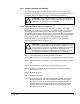
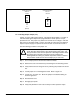
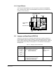
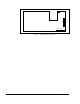
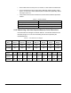
Figure 2.6 - Jumper J17 Settings for Analog Outputs
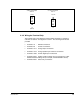
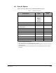
2.4.2 Wiring the Terminal Strip
The terminal strip on the Regulator board provides terminals for connecting
customer I/O devices. See figures 2.4 and 2.7. The following terminals are
provided:
• Terminals 1-3 : RS-232 connections
• Terminals 4-9 : encoder connections
• Terminals 10-11: analog output connections
• Terminals 12-15: analog speed/torque reference connections
• Terminals 16-25: 24 VDC digital input connections
• Terminals 26-27: snubber resistor braking control connections for older
Snubber Resistor Braking Kits (for example, the M/N 2DB2010 series)
• Terminals 28-31: status relay connections
Voltage Output Option
Pins 2-3
10 VDC
J17
Current Output Option
Pins 1-2
4
-
20 mA
J17
(default)