
User Manual


V
Table of Contents
List of Tables
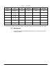
Table 2.1 – Power Ratings .............................................................................. 2-2
Table 2.2 – Settings of Jumpers on Base Board ............................................. 2-11
Table 2.3 – Available Kits and Options ........................................................... 2-13
Table 3.1 – Ambient Conditions ...................................................................... 3-2
Table 3.2 – Drive Dimensions and Weights .................................................... 3-2
Table 3.3 – Recommended Power Wire Sizes for 30 to 50 HP Drives ........... 3-5
Table 3.4 – Recommended Power Wire Sizes for 60 to 100 HP Drives ......... 3-6
Table 3.5 – Recommended Terminal Strip Wire Sizes ................................... 3-6
Table 3.6 – Motor Lead Lengths ...................................................................... 3-7
Table 3.7 – Reactors ....................................................................................... 3-7
Table 3.8 – AC Input Line Fuse Selection Values ........................................... 3-8
Table 3.9 – Circuit Breaker Selection Values .................................................. 3-9
Table 3.10 – AC Reactor Selection Values ....................................................... 3-9
Table 5.1 – AC Line Reactors ......................................................................... 5-2
Table 7.1 – RS-232 Connections (Terminals 1-3) ........................................... 7-1
Table 7.2 – Encoder Connections (Terminals 4-9).......................................... 7-1
Table 7.3 – Analog Output Connections (Terminals 10 and 11) ..................... 7-2
Table 7.4 – Analog Speed/Torque Reference Connections
(Terminals 12-15) ......................................................................... 7-2
Table 7.5 – Digital Input Connections (Terminals 16-25) ................................ 7-2
Table 7.6 – Snubber Resistor Braking Connections (Terminals 26 and 27) ... 7-3
Table 7.7 – Status Relay Connections (Terminals 28-31) .............................. 7-3
Table 7.8 – Wiring Signal and Control I/O to the Terminal Strip ..................... 7-9
Table 9.1 – Resistance Checks ....................................................................... 9-3
Table 9.2 – Replacement Parts for the GV3000/SE Drives ............................ 9-4
Table A.1 – Service Conditions ........................................................................ A-1
Table A.2 – Environmental Condition .............................................................. A-2
Table A.3 – Terminal Strip Input Specifications ............................................... A-2
Table A.4 – Terminal Strip Output Specifications ............................................ A-2
Table A.5 – Terminal Strip RS-232 Specifications........................................... A-3
Table A.6 – Encoder Feedback Device Specifications
(FVC Regulation Only) ................................................................. A-3
Table A.7 – Input Signal Response Times (Maximum) ................................... A-4