
Install, Troubleshooting User guide


7-15
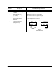
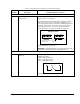
Wiring the Regulator Board Terminal Strip
Description
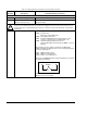
Digital Input 5
(Function Loss)
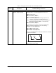
Digital Input 4
(Run/Jog)
Parameters/Wiring Connections
The following parameters must be set:
P.026: Function Loss Response
A signal must be present at terminal 20 for the drive to be able to
start. See figures 7.1 and 7.2 The drive is shipped from the
factory with a jumper between terminals 16 and 20 which provides
the signal. The function loss input should be in series with the
drive's external interlocks. In this case, the jumper must be
removed before the connections are made. See figure 2.8.
Terminal 20 On = No Function Loss
IMPORTANT : A maintained function loss switch should be used
if P.054 (Level Sense Start Enable) = ON and P.026 = 1.
The following parameters must be set:
P.000: Control Source
P.020: Jog Speed Reference
P.021: Jog Ramp Accel Time
P.022: Jog Ramp Decel Time
Terminal 21 On = Jog Operation
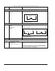
Wiring a Run/Jog Input
Table 7.8 – Wiring Signal and Control I/O to the Terminal Strip (Continued)
Terminal
Number
20
21
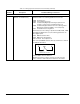
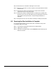
Wiring a Function Loss Input
16 17 18 19 20 21 16 17 18 19 20 21
REMOVE FACTORY FUNCTION
LOSS JUMPER HERE.
FUNCTION LOSS
COAST-STOP
PUSH-BUTTON
SAFETY INTERLOCKS
TERMINAL STRIP
16 21
RUN
JOG