
Install, Troubleshooting User guide


2-7
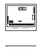
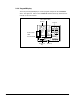
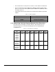
About the Drive
Figure 2.5 – Regulator Board Components and Locations
USER DISPLAY
12345678910111213141516171819202122232425262728293031
34-Pin Ribbon Cable
J3
J8
J7
J17 J4
USER I/O TERMINAL STRIP
J9
J5
26-Pin Ribbon Cable
J3 - Option Board Connector
J4 - Analog Input Jumper
J5 - Power Module Feedback Cable
J7 - OIM (optional) Connector
J8 - RS232C Port
J9 - Keypad/Display Connector
J17 - Analog Output Jumper