
Hardware Ref, Installation, and Troubleshooting Owner's manual

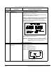
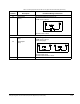


Wiring Optional User-Supplied Braking Resistors
8-3
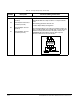
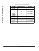
8.2 Selecting a Braking Resistor
The maximum braking power is defined by the maximum braking current and the
maximum DC voltage (750 V). To determine the correct braking resistor for your drive,
refer to table 8.2.
Table 8.2 – Selecting a Braking Resistor
Drive M/N
Braking Power
1
Maximum
Braking
Current
Power
Module Input
Vol tage
Turn-On
Vol tage
Turn-Off
Vol tage
Minimum
Allowed
External
Braking
ResistorContinuous
25% Duty
Cycle
31ER40xx
31ET40xx
4.5 kW 4.5 kW 6 A 460 V 750 V 720 V 125.0 Ω
38ER40xx
38ET40xx
4.5 kW 4.5 kW 6 A 460 V 750 V 720 V 125.0 Ω
55ER40xx
55ET40xx
4.5 kW 4.5 kW 6 A 460 V 750 V 720 V 125.0 Ω
85ER40xx
85ET40xx
4.5 kW 4.5 kW 6 A 460 V 750 V 720 V 125.0 Ω
126ER40xx
126ET40xx
7.5 kW 7.5 kW 10 A 460 V 750 V 720 V 75.0 Ω
150ER40xx
150ET40xx
7.5 kW 7.5 kW 10 A 460 V 750 V 720 V 75.0 Ω
240ER40xx
240ET40xx
11 kW 11 kW 15 A 460 V 750 V 720 V 50.0 Ω
300ER40xx
300ET40xx
15 kW 15 kW 20 A 460 V 750 V 720 V 37.5 Ω
430ER40xx
430ET40xx
22 kW 22 kW 30 A 460 V 750 V 720 V 25.0 Ω
1
The turn-on and the turn-off voltage and the braking power is proportional to the AC line voltage (specified
in parameter H.021 or U.018).