
Hardware Ref, Installation, and Troubleshooting Owner's manual


Wiring the Regulator Board Terminal Strip and the Output Relay Terminal Strip
7-3
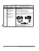
Figure 7.1 – Two-Wire Start/Stop Sample Control Wiring
+/- 10, 0 to 10 VDC Speed or Tor
q
ue Reference
Isolated Reference Ground
7
10
11
12
13
14
15
16
17
19
20
22
23
24
9
21
+15 VDC
Phase A
Phase A Not
Phase B
Phase B Not
Re
g
ulator Common
4
5
6
8
25
18
0 to 10 VDC Analo
g
Output
Analo
g
Output Return
Isolated Reference Volta
g
e
0/4 to 20 mA Speed or Tor
q
ue Reference
+24 VDC Suppl
y
Di
g
ital Input 8
(
Local/Remote
)
Di
g
ital Input 7
(
Ramp 1/ Ramp 2
)
Di
g
ital Input 6
(
Forward/Reverse
)
Di
g
ital Input 5
(
Function Loss
)
Di
g
ital Input 4
(
Run/Jo
g)
Di
g
ital Input 3
(
Fault Reset
)
Di
g
ital Input 2
(
Stop
)
Di
g
ital Input 1
(
Start
)
+24 VDC Common
FWD
REV
Function Loss
Start/Stop
Reset
Run
Jog
Important:
A maintained function loss switch
should be used if P.054 (Level Sense Start
Enable) = ON and P.026 (Function Loss
Response) = 1.
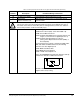
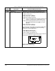
Figure 7.2 – Three-Wire Start/Stop Sample Control Wiring
+/- 10, 0 to 10 VDC Speed or Tor
q
ue Reference
Isolated Reference Ground
7
10
11
12
13
14
15
16
17
19
20
22
23
24
9
21
+15 VDC
Phase A
Phase A Not
Phase B
Phase B Not
Re
g
ulator Common
4
5
6
8
25
18
0 to 10 VDC Analo
g
Output
Analo
g
Output Return
Isolated Reference Volta
g
e
0/4 to 20 mA Speed or Tor
q
ue Reference
+24 VDC Suppl
y
Di
g
ital Input 8
(
Local/Remote
)
Di
g
ital Input 7
(
Ramp 1/ Ramp 2
)
Di
g
ital Input 6
(
Forward/Reverse
)
Di
g
ital Input 5
(
Function Loss
)
Di
g
ital Input 4
(
Run/Jo
g)
Di
g
ital Input 3
(
Fault Reset
)
Di
g
ital Input 2
(
Stop
)
Di
g
ital Input 1
(
Start
)
+24 VDC Common
FWD
REV
Function Loss
Stop
Start
Reset
Run
Jog
Important:
A maintained function loss switch
should be used if P.054 (Level Sense Start
Enable) = ON and P.026 (Function Loss
Response) = 1.