
Hardware Ref, Installation, and Troubleshooting Owner's manual


2-12
GV3000/SE AC Bookshelf Drive Hardware Reference, Version 6.06
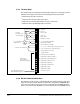
2.8 Output Relay Terminal Strip
The output relay terminal strip, located on the Power board, provides a set of Form A
and B contacts. These contacts are the under control of the user via programmable
parameters. A Form A or B transition can be used to indicate drive status. The
contacts are rated for 2 amps resistive load at 250 VAC/ 30 VDC. See figure 2.11
2.9 Internal Braking Transistor
An internal braking transistor connects externally mounted, user-supplied braking
resistors to the DC bus and prevents DC bus overvoltage faults. The resistor switches
on during motor regeneration. See chapter 8 for more information.
2.10 Optional Internal AC Mains Filter
A built-in line filter limits radio frequency emission to EMC permitted values. It provides
the same function as a line reactor.
An AC Mains Filter is required if the installation must be in compliance with the
European Community Electromagnetic Compatibility Standard. See Appendix C for
more information.
2.11 Optional Equipment
Table 2.2 lists standard GV3000/SE kits and options.
Figure 2.11 – Output Relay Terminal Strip
31
28
29
30
N. C. Rela
y
Contact
N. C. Rela
y
Common
N. O. Rela
y
Contact
N. O. Rela
y
Common
Table 2.2 – Standard Kits and Options
Description Model Number Instruction Manual
Motor Encoder Cable
2TC3025
2TC3075
2TC4025
2TC4075
2TC4100
2TC4300
D2-3305
ControlNet Network Option Board 2CN3000 D2-3390
InterBus Network Option Board 2NB3000 49’1333
AutoMax Network Option Board with
762mm (30”) of Cable
2AX3000 D2-3308
AutoMax RS-232 Adapter Cable 2CA3001 D2-3348