
Hardware Ref, Installation, and Troubleshooting Owner's manual


2-10
GV3000/SE AC Bookshelf Drive Hardware Reference, Version 6.06
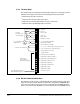
2.6.2 Terminal Strip
The terminal strip on the Regulator board provides terminals for connecting customer
I/O devices. See figures 2.6 and 2.9. The following terminals are provided:
•
Terminals 4-9: Encoder connections
•
Terminals 10-11: Analog output connections
•
Terminals 12-15: Analog speed/torque reference connections
•
Terminals 16-25: 24V DC digital input connections
2.6.3 RS-232 Communication Port
The Regulator board contains a 9-pin D-shell RS-232 communication port (X8). See
figure 2.6. This port provides RS-232 communication between the GV3000/SE drive
and a personal computer running the Control and Configuration (CS3000) Software.
Refer to instruction manual D2-3348 for more information about the CS3000 software.
Figure 2.9 – Typical Terminal Strip Connections
+/- 10, 0 to 10 VDC Speed or Tor
q
ue Reference
Isolated Reference Ground
7
10
11
12
13
14
15
16
17
19
20
22
23
24
9
21
+15 VDC
Phase A
Phase A Not
Phase B
Phase B Not
Re
g
ulator Common
4
5
6
8
25
18
0 to 10 VDC Analo
g
Output
Analo
g
Output Return
Isolated Reference Volta
g
e
0/4 to 20 mA Speed or Tor
q
ue Reference
+24 VDC Suppl
y
Di
g
ital Input 8
(
Local/Remote
)
Di
g
ital Input 7
(
Ramp 1/ Ramp 2
)
Di
g
ital Input 6
(
Forward/Reverse
)
Di
g
ital Input 5
(
Function Loss
)
Di
g
ital Input 4
(
Run/Jo
g)
Di
g
ital Input 3
(
Fault Reset
)
Di
g
ital Input 2
(
Stop
)
Di
g
ital Input 1
(
Start
)
+24 VDC Common
Encoder
Feedback and
15 VDC Suppl
y
0 to 10 VDC Meter
or Other Device
Reference Potentiometer
Di
g
ital Inputs
(
6, 7, and 8 are
Software-Assi
g
nable
)
Use with Di
g
ital Inputs 1-8
When Externall
y
Powered