
Reference Manual User guide


A-4
GV3000/SE 230 VAC Drive, Software Reference Version 6.04
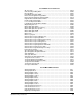
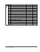
Second Menu RMI Parameters
(continued)
Digital Output 1 Configuration........................................................................... r.031
Digital Output 1 Delay Time .............................................................................. r.040
Digital Output 2 Configuration........................................................................... r.032
Digital Output 2 Delay Time .............................................................................. r.041
Digital Output 3 Configuration........................................................................... r.033
Digital Output 3 Delay Time .............................................................................. r.042
Digital Output 4 Configuration........................................................................... r.034
Digital Output 4 Delay Time .............................................................................. r.043
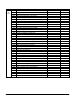
Frequency Input Gain ....................................................................................... r.016
Frequency Input Offset ..................................................................................... r.015
Frequency Input Sample Period ....................................................................... r.014
Low Speed Detection Level .............................................................................. r.056
PI Regulator Integral Gain ................................................................................ r.022
PI Regulator Offset ........................................................................................... r.020
PI Regulator Proportional Gain ......................................................................... r.021
Relay Output 1 (NO) Configuration................................................................... r.035
Relay Output 1 Delay Time ............................................................................... r.044
Relay Output 2 (NO/NC) Configuration ............................................................ r.036
Relay Output 2 Delay Time ............................................................................... r.045
Relay Output 3 (NO/NC) Configuration ............................................................ r.037
Relay Output 3 Delay Time ............................................................................... r.046
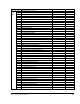
Speed Detection Hysteresis Band .................................................................... r.053
Speed Detection Level 1 ................................................................................... r.050
Speed Detection Level 2 ................................................................................... r.051
Speed Detection Level 3 ................................................................................... r.052
Torque Detection Hysteresis............................................................................. r.066
Torque Detection Level 1 .................................................................................. r.063
Torque Detection Level 2 .................................................................................. r.064
Torque Detection Level 3 .................................................................................. r.065
Torque/Current Limit Source............................................................................. r.025
Refer to the Remote Meter Interface board manual (D2-3341) for the RMI parameter
descriptions.