
Software Start-Up and Ref. Owner manual
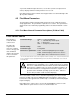
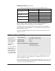
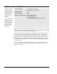
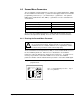
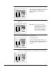
Table Of Contents
- GV3000/SE AC General Purpose (V/Hz) and Vector Duty Drive, 1 - 20 HP, 230V AC Software Start-Up and Reference Manual D2-3387-5
- Important User Information
- Document Update
- Summary of Changes
- Table of Contents
- List of Figures
- List of Tables
- Preface
- Chapter 1 - Starting Up the Drive for Volts/Hertz Regulation
- Chapter 2 - Starting Up the Drive for Vector Regulation
- Chapter 3 - Using the Keypad/Display To Program, Monitor, and Control the Drive
- Chapter 4 - Programming Reference
- Chapter 5 - Troubleshooting the Drive Using Error Codes
- Appendix A - Alphabetical Listing of Parameters
- Appendix B - Record of User Parameter Settings
- Appendix C - Power Module-Dependent Parameter Default Values (230 V Series)
- Appendix D - Default Parameter Settings
- Appendix E - Configuring the Digital Inputs When the RMI Board Is Installed in the Drive
- Appendix F - Using the Terminal Strip Analog Input
- Appendix G - Drive Regulation Overview
- Back Cover / Publication D2-3387-5 July 2013

4-7
Programming Reference
Control Source (P.000)
Local keypad/display
(P.000 = LOCL)
Terminal strip remote inputs
(P.000 = rE)
Option port (P.000 = OP)
Serial port (P.000 = SErL)
AUTO/MAN Status
AUTO selected
MAN selected
AUTO selected
MAN selected
AUTO selected
MAN selected
AUTO selected
MAN selected
Speed Reference Source
Terminal strip
Local keypad/display or OIM
Terminal strip
Local keypad/display or OIM
Network
Local keypad/display or OIM
Terminal strip
Local keypad/display or OIM
P.000 Control Source
(continued)
Table 4.1 – Speed Reference Source Based on P.000 and AUTO/MAN Key Status
Refer to chapter 3 and the description of parameter P.052 (AUTO/MAN Key
Disable) in chapter 4 for more information on the AUTO/MAN key.
Set P.000 = OP to select the DeviceNet
TM
Network option board, the AutoMax
TM
Network option board, the PROFIBUS
TM
, or the ControlNet
TM
Network option board
as the drive control source.
Note that the REMOTE LED will turn on if any control source other than the local
keypad is selected.
P.001 Accel Time 1 (RAMP 1)
For V/Hz regulation,
this parameter
specifies the amount
of time in which the
motor ramps from
zero speed to
Maximum Speed
(P.004).
For vector regulation,
this parameter
specifies the amount
of time in which the
motor ramps from
zero speed to Motor
Top Speed (U.017).
Parameter Range: 1.0 to 999.9 seconds (V/Hz)
0.1 to 999.9 seconds (vector)
Default Setting: 20.0
Parameter Type: Tunable
Refer also to parameters: P.004 Maximum Speed
P.005 Current Limit
U.017 Motor Top Speed
The time the motor takes to make any speed increase is directly proportional to the
value in this parameter. This parameter does not apply if JOG is selected. See
P.021 (Jog Ramp Accel Time).
If the motor load inertia is high, or the Current Limit (P.005) setting is too low, actual
motor acceleration time will be longer than the time set in P.001. If Accel Time 1 is
set too short, an overcurrent fault may occur.