
Software Start-Up and Ref. Owner manual
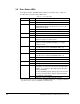

Table Of Contents
- GV3000/SE AC General Purpose (V/Hz) and Vector Duty Drive, 1 - 20 HP, 230V AC Software Start-Up and Reference Manual D2-3387-5
- Important User Information
- Document Update
- Summary of Changes
- Table of Contents
- List of Figures
- List of Tables
- Preface
- Chapter 1 - Starting Up the Drive for Volts/Hertz Regulation
- Chapter 2 - Starting Up the Drive for Vector Regulation
- Chapter 3 - Using the Keypad/Display To Program, Monitor, and Control the Drive
- Chapter 4 - Programming Reference
- Chapter 5 - Troubleshooting the Drive Using Error Codes
- Appendix A - Alphabetical Listing of Parameters
- Appendix B - Record of User Parameter Settings
- Appendix C - Power Module-Dependent Parameter Default Values (230 V Series)
- Appendix D - Default Parameter Settings
- Appendix E - Configuring the Digital Inputs When the RMI Board Is Installed in the Drive
- Appendix F - Using the Terminal Strip Analog Input
- Appendix G - Drive Regulation Overview
- Back Cover / Publication D2-3387-5 July 2013
3-9
Using the Keypad/Display To Program, Monitor, and Control the Drive
Table 3.3 describes the values that will be displayed when the corresponding
monitor mode LED is on.
Table 3.3 - Monitor Mode LEDs
Monitor Mode LED
SPEED
VOLTS
AMPS
HZ
KW
TORQUE
ALL LEDs
Corresponding Display When LED is ON (Actual Values)
Motor speed is displayed. This value is scaled in parameter
P.028.
Drive output volts are displayed. This value is not DC bus
volts.
Drive output amps are displayed.
Drive output frequency in hertz is displayed.
Output power of the drive in kilowatts is displayed. Note
that this is intended for display purposes as a general
indication of kilowatt output and should not be used for
control or exact metering purposes.
Motor output torque is displayed in percent. (Valid only for
vector regulation).
Selected speed reference (in P.028 units) or torque
reference (in %) is displayed.