
Software Start-Up and Ref. Owner manual
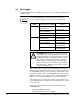
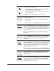
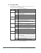

Table Of Contents
- GV3000/SE AC General Purpose (V/Hz) and Vector Duty Drive, 1 - 20 HP, 230V AC Software Start-Up and Reference Manual D2-3387-5
- Important User Information
- Document Update
- Summary of Changes
- Table of Contents
- List of Figures
- List of Tables
- Preface
- Chapter 1 - Starting Up the Drive for Volts/Hertz Regulation
- Chapter 2 - Starting Up the Drive for Vector Regulation
- Chapter 3 - Using the Keypad/Display To Program, Monitor, and Control the Drive
- Chapter 4 - Programming Reference
- Chapter 5 - Troubleshooting the Drive Using Error Codes
- Appendix A - Alphabetical Listing of Parameters
- Appendix B - Record of User Parameter Settings
- Appendix C - Power Module-Dependent Parameter Default Values (230 V Series)
- Appendix D - Default Parameter Settings
- Appendix E - Configuring the Digital Inputs When the RMI Board Is Installed in the Drive
- Appendix F - Using the Terminal Strip Analog Input
- Appendix G - Drive Regulation Overview
- Back Cover / Publication D2-3387-5 July 2013
3-8
GV3000/SE 230 VAC Drive, Software Reference Version 6.04
Meaning
Output power is being applied to the motor.
Output power is not being applied to the motor.
The drive is being controlled (START, RUN/JOG,
FORWARD/REVERSE, speed reference) from a source
other than the keypad.
The drive is being controlled from the keypad.
The network connection is lost.
Jog is selected.
Run is selected.
The drive is receiving its speed reference from the
terminal strip input or network option.
The drive is receiving its speed reference from the local
keypad or serial port (OIM or CS3000), i.e., using a
manual reference.
The requested motor direction is forward; the actual
motor direction is reverse (REVERSE LED is on).
The motor is running in the forward direction.
The motor direction is not forward.
The requested motor direction is reverse; the actual
motor direction is forward (FORWARD LED is on).
The motor is running in the reverse direction.
The motor direction is not reverse.
The keypad/display is in program mode.
The keypad/display is in monitor mode.
Parameters cannot be modified from the keypad without
entering the correct password into P.051 (Programming
Disable). See section 4.4, Ensuring Program Security,
for more information.
Note that disabling program changes by means of P.051
does not prevent parameter changes being made from
the serial port or the network.
Parameters can be modified from the keypad.
3.6 Drive Status LEDs
The keypad contains eight LEDs that show the present drive status. Table 3.2
describes what each drive status LED means.
Table 3.2 – Drive Status LEDs
LED
RUNNING
REMOTE
JOG
AUTO
FORWARD
1
REVERSE
1
PROGRAM
PASSWORD
Status
On
Off
On
Off
Flashing
On
Off
On
Off
Flashing
On
Off
Flashing
On
Off
On
Off
On
Off
1
If the speed reference is zero (0), pressing the FORWARD/REVERSE key (or toggling the FWD/REV
input) will not alter the state of the FORWARD or REVERSE LEDS.