
Software Start-Up and Ref. Owner manual
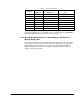

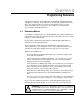
Table Of Contents
- GV3000/SE AC General Purpose (V/Hz) and Vector Duty Drive, 1 - 20 HP, 230V AC Software Start-Up and Reference Manual D2-3387-5
- Important User Information
- Document Update
- Summary of Changes
- Table of Contents
- List of Figures
- List of Tables
- Preface
- Chapter 1 - Starting Up the Drive for Volts/Hertz Regulation
- Chapter 2 - Starting Up the Drive for Vector Regulation
- Chapter 3 - Using the Keypad/Display To Program, Monitor, and Control the Drive
- Chapter 4 - Programming Reference
- Chapter 5 - Troubleshooting the Drive Using Error Codes
- Appendix A - Alphabetical Listing of Parameters
- Appendix B - Record of User Parameter Settings
- Appendix C - Power Module-Dependent Parameter Default Values (230 V Series)
- Appendix D - Default Parameter Settings
- Appendix E - Configuring the Digital Inputs When the RMI Board Is Installed in the Drive
- Appendix F - Using the Terminal Strip Analog Input
- Appendix G - Drive Regulation Overview
- Back Cover / Publication D2-3387-5 July 2013

3-5
Using the Keypad/Display To Program, Monitor, and Control the Drive
Example
A
B
C
D
E
F
G
H
If the actual
number is...
1000.5
-999
-1000
-99.9
-1000.5
-9.99
-100.25
-9.999
It will appear on the
display as...
1000.
-999
1000
-99.9
1000.
-9.99
100.2
9.999
And the SPEED LED
will...
Not flash
Not flash
Flash
Not flash
Flash
Not flash
Flash
Flash
Table 3.1 – Display Range Examples
This does not apply for the speed display. For the speed display, the FORWARD or
REVERSE LEDs indicate actual speed reference polarity.
3.4.2 Scaling the Manual Reference, Speed Display, and Reference
Display Using P.028
In versions 5.0 and later, the values displayed for the manual reference, the output
speed, and the selected speed reference represent relative speed as opposed to
always being displayed in RPM. These values are scaled using P.028 (Speed
Display Scaling). Refer to the Speed Display Scaling parameter description in
chapter 4 for more information.