
Software Start-Up and Ref. Owner manual
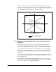


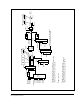
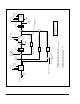
Table Of Contents
- GV3000/SE AC General Purpose (V/Hz) and Vector Duty Drive, 1 - 20 HP, 230V AC Software Start-Up and Reference Manual D2-3387-5
- Important User Information
- Document Update
- Summary of Changes
- Table of Contents
- List of Figures
- List of Tables
- Preface
- Chapter 1 - Starting Up the Drive for Volts/Hertz Regulation
- Chapter 2 - Starting Up the Drive for Vector Regulation
- Chapter 3 - Using the Keypad/Display To Program, Monitor, and Control the Drive
- Chapter 4 - Programming Reference
- Chapter 5 - Troubleshooting the Drive Using Error Codes
- Appendix A - Alphabetical Listing of Parameters
- Appendix B - Record of User Parameter Settings
- Appendix C - Power Module-Dependent Parameter Default Values (230 V Series)
- Appendix D - Default Parameter Settings
- Appendix E - Configuring the Digital Inputs When the RMI Board Is Installed in the Drive
- Appendix F - Using the Terminal Strip Analog Input
- Appendix G - Drive Regulation Overview
- Back Cover / Publication D2-3387-5 July 2013
G-6
GV3000/SE 230 VAC Drive, Software Reference Version 6.04
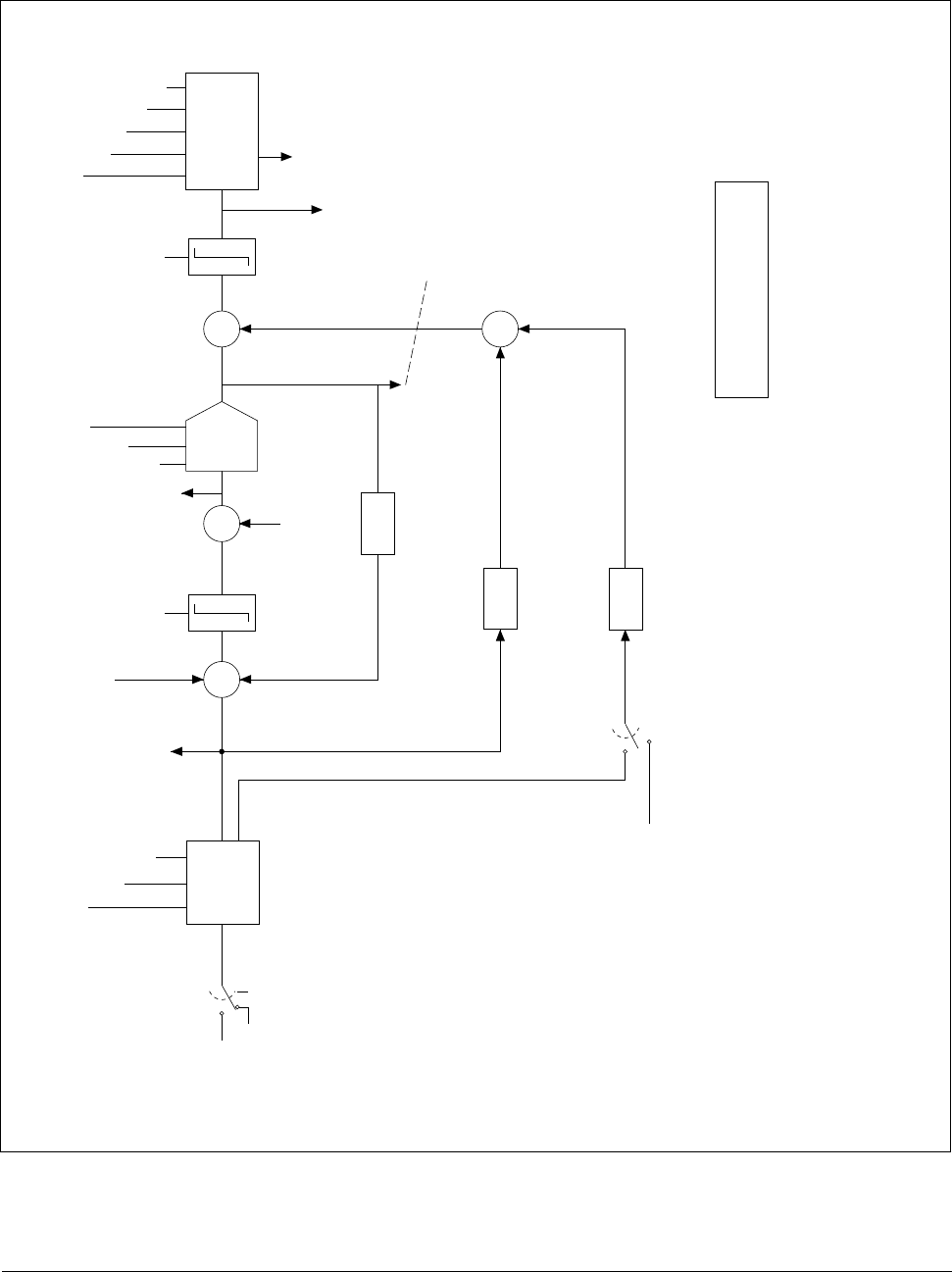
Figure G.5 – Vector Regulator: Speed Loop Detail
Speed Ref
0
Ramp
Stop
S-curve
P.001/017
P.002/018
P.019
(To Outer
Control Loop)
*
*
*
*
*
OCL output
(from OCL
block diag.)
+
+
+
+
+
+
+
–
–
+/-U.017
PI
Ki Kp Lim
U.013
U.012
Speed PI limits
Spd fdbk
x U.026
x U.028
Speed PI
Output
x U.027
Current
compounding
Losses compensation
Inertia compensation (WR
2
)
0
1
Network Inertia comp
2
enable
Network Inertia comp
1
(To Outer Control
Loop)
Iq ref limits
Torque
reference
Rate
output
Iq Fdbk
Torque
Controller
U.032
U.020
U.019
U.014
U.015
1
If AutoMax option, the drop 1, register 35
If ControlNet option, then fourth work of scheduled data
2
If AutoMax option, the drop 1, register 53, bit 1
If ControlNet option, then N10:30 bit 1
*Available in network option
read registers