
Software Start-Up and Ref. Owner manual
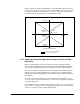


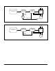
Table Of Contents
- GV3000/SE AC General Purpose (V/Hz) and Vector Duty Drive, 1 - 20 HP, 230V AC Software Start-Up and Reference Manual D2-3387-5
- Important User Information
- Document Update
- Summary of Changes
- Table of Contents
- List of Figures
- List of Tables
- Preface
- Chapter 1 - Starting Up the Drive for Volts/Hertz Regulation
- Chapter 2 - Starting Up the Drive for Vector Regulation
- Chapter 3 - Using the Keypad/Display To Program, Monitor, and Control the Drive
- Chapter 4 - Programming Reference
- Chapter 5 - Troubleshooting the Drive Using Error Codes
- Appendix A - Alphabetical Listing of Parameters
- Appendix B - Record of User Parameter Settings
- Appendix C - Power Module-Dependent Parameter Default Values (230 V Series)
- Appendix D - Default Parameter Settings
- Appendix E - Configuring the Digital Inputs When the RMI Board Is Installed in the Drive
- Appendix F - Using the Terminal Strip Analog Input
- Appendix G - Drive Regulation Overview
- Back Cover / Publication D2-3387-5 July 2013

G-2
GV3000/SE 230 VAC Drive, Software Reference Version 6.04
If a network option board is installed, the reference comes from the network trim
reference register which can be configured as a direct or broadcast register. If a
Remote Meter Interface (RMI) board is installed, the reference is always the RMI
analog input. If there is no option board installed, the reference is Preset Speed 8
(P.038).
The OCL feedback is either the drive's scaled terminal strip analog input (default) or
the speed loop PI output (user option). The feedback is fed through a lead/lag block
which can be configured as a lead/lag, lag/lead, or null (bypass) function.
If a network option board is installed in the drive, the OCL enable signal is controlled
by a bit in the drive control word. If an RMI board is installed, the OCL enable signal
is controlled by the RMI digital input (configured for RMI PI regulator enable) or by
the same internal signal used to control the speed loop enable signal. (Refer to the
r.030 parameter description in the RMI instruction manual, D2-3341, for more
information.)
If the drive is running and the OCL enable signal is on (closed), the outer loop will
operate. If the enable signal is off (open) or the drive is not running, the outer loop
is held in reset.
If there is no option board installed, the OCL is enabled when the drive is running
(that is, the speed and torque controllers are active) and is disabled if the drive is
stopped.