
Software Start-Up and Ref. Owner manual
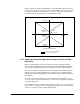

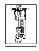
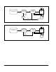
Table Of Contents
- GV3000/SE AC General Purpose (V/Hz) and Vector Duty Drive, 1 - 20 HP, 230V AC Software Start-Up and Reference Manual D2-3387-5
- Important User Information
- Document Update
- Summary of Changes
- Table of Contents
- List of Figures
- List of Tables
- Preface
- Chapter 1 - Starting Up the Drive for Volts/Hertz Regulation
- Chapter 2 - Starting Up the Drive for Vector Regulation
- Chapter 3 - Using the Keypad/Display To Program, Monitor, and Control the Drive
- Chapter 4 - Programming Reference
- Chapter 5 - Troubleshooting the Drive Using Error Codes
- Appendix A - Alphabetical Listing of Parameters
- Appendix B - Record of User Parameter Settings
- Appendix C - Power Module-Dependent Parameter Default Values (230 V Series)
- Appendix D - Default Parameter Settings
- Appendix E - Configuring the Digital Inputs When the RMI Board Is Installed in the Drive
- Appendix F - Using the Terminal Strip Analog Input
- Appendix G - Drive Regulation Overview
- Back Cover / Publication D2-3387-5 July 2013

F-4
GV3000/SE 230 VAC Drive, Software Reference Version 6.04
To adjust the offset (P.009):
Step 1. Verify that the analog input is configured as the speed reference control
source (P.000 = rE (or AUTO is selected), P.008 = 0, and U.000 = 0).
Step 2. Display the converted value of the analog input using the selected speed
reference display mode. (Refer to chapter 3 for the procedure for
displaying the selected speed reference.)
Step 3. Adjust P.009 to achieve the value of minimum speed when the analog input
is set to the position where minimum speed is desired.
The gain parameter is typically used to compensate for saturation or insufficient
voltage from the input source.
Unless the input is a 4 to 20 mA signal, before adjusting the gain, set P.011 to 0 to
avoid clamping the reference at 0. After adjusting P.009 and P.010, change P.011
to reflect the intended input.
To adjust the gain (P.010):
Step 1. Verify that the analog input is configured as the speed reference control
source (P.000 = rE (or AUTO is selected), P.008 = 0, and U.000 = 0).
Step 2. Display the converted value of the analog input using the selected speed
reference display mode. (Refer to chapter 3 for the procedure for
displaying the selected speed reference.)
Step 3. Adjust P.010 to achieve the value of maximum speed when the analog
input is set to the position where maximum speed is desired. For
example, if a speed pot is used, rotate the pot to its maximum position.
The adjustment range for P.010 is 0.100 to 5.000.
F.3 Using the Analog Input for Vector Torque Reference
(U.000 = 1)
When the analog input is used as the vector control torque reference (U.000 = 1),
the analog input value will be interpreted internally as shown in table F.2 and
described below. Note that P.009 and P.010 are not used when U.001=1.
Parameter P.011 is used only to enable the analog input signal loss detection
feature.
Table F.2 – Analog Input Conversion Scaling for Torque Reference
Analog Input
Value
+10 VDC (20 mA)
0 VDC (0 mA)
-10 VDC
Corresponding Internal Value
Positive torque limit of the drive. (+150% of the rated motor
torque.)
Zero torque reference.
Negative torque limit of the drive. (-150% of the rated motor
torque.)
• The maximum positive analog input value (+10 VDC or 20 mA) corresponds to
the positive torque limit of the drive (+150% of the rated motor torque).