
Software Start-Up and Ref. Owner manual
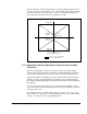

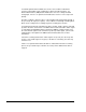
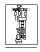
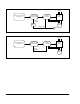
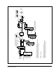
Table Of Contents
- GV3000/SE AC General Purpose (V/Hz) and Vector Duty Drive, 1 - 20 HP, 230V AC Software Start-Up and Reference Manual D2-3387-5
- Important User Information
- Document Update
- Summary of Changes
- Table of Contents
- List of Figures
- List of Tables
- Preface
- Chapter 1 - Starting Up the Drive for Volts/Hertz Regulation
- Chapter 2 - Starting Up the Drive for Vector Regulation
- Chapter 3 - Using the Keypad/Display To Program, Monitor, and Control the Drive
- Chapter 4 - Programming Reference
- Chapter 5 - Troubleshooting the Drive Using Error Codes
- Appendix A - Alphabetical Listing of Parameters
- Appendix B - Record of User Parameter Settings
- Appendix C - Power Module-Dependent Parameter Default Values (230 V Series)
- Appendix D - Default Parameter Settings
- Appendix E - Configuring the Digital Inputs When the RMI Board Is Installed in the Drive
- Appendix F - Using the Terminal Strip Analog Input
- Appendix G - Drive Regulation Overview
- Back Cover / Publication D2-3387-5 July 2013
F-3
Using the Terminal Strip Analog Input
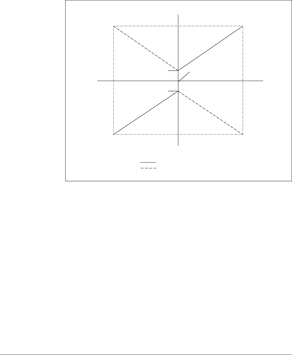
Figure F.2 illustrates how the analog signal is scaled internally by the drive when it
is used as the speed or trim reference. The solid line indicates the conversion when
the non-inverted state is selected (P.011 is even). The dashed line indicates the
conversion when the inverted state is selected (P.011 is odd).
Figure F.2 – Analog Input Conversion Scaling (Speed or Trim Reference)
F.2.1 Adjusting for External Signal Errors Using the Offset and Gain
Parameters
When the analog input is used for speed or trim reference, parameters P.009
(Terminal Strip Analog Input Offset) and P.010 (Terminal Strip Analog Input Gain)
can be used to compensate for any offset or gain errors in the external circuitry.
The value in P.009 is first added to the converted 10-bit value and then the gain is
applied. If an offset or gain adjustment is needed, the offset should be adjusted
first, with the minimum input applied, and the gain adjusted last, with the maximum
input applied.
To remove a positive external offset, enter a negative value into P.009. In most
cases, the offset is left at the default value of zero and is only adjusted to counteract
external circuitry errors.
The adjustment range for P.009 is -900 to +900. For 0 to 10 V (or -10 V to +10 V)
input, a value of +1 equals an offset of approximately 10 mV. For 0 to 20 mA input,
a value of +1 equals an offset of approximately 20 µA.
+Max Spd
(P.004)
+Min Spd
(P.003)
-Min Spd
(P.003)
-10 vdc
+10 vdc
+20 ma
0 VDC
0 to 4 mA
-Max Spd
(P.004)
Terminal Strip Analog Input
P.011 is even = not inverted
P.011 is odd = inverted