
Software Start-Up and Ref. Owner manual
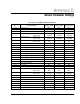
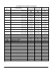
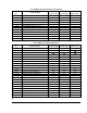
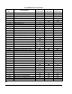
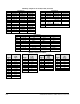

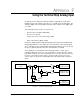
Table Of Contents
- GV3000/SE AC General Purpose (V/Hz) and Vector Duty Drive, 1 - 20 HP, 230V AC Software Start-Up and Reference Manual D2-3387-5
- Important User Information
- Document Update
- Summary of Changes
- Table of Contents
- List of Figures
- List of Tables
- Preface
- Chapter 1 - Starting Up the Drive for Volts/Hertz Regulation
- Chapter 2 - Starting Up the Drive for Vector Regulation
- Chapter 3 - Using the Keypad/Display To Program, Monitor, and Control the Drive
- Chapter 4 - Programming Reference
- Chapter 5 - Troubleshooting the Drive Using Error Codes
- Appendix A - Alphabetical Listing of Parameters
- Appendix B - Record of User Parameter Settings
- Appendix C - Power Module-Dependent Parameter Default Values (230 V Series)
- Appendix D - Default Parameter Settings
- Appendix E - Configuring the Digital Inputs When the RMI Board Is Installed in the Drive
- Appendix F - Using the Terminal Strip Analog Input
- Appendix G - Drive Regulation Overview
- Back Cover / Publication D2-3387-5 July 2013
F-2
GV3000/SE 230 VAC Drive, Software Reference Version 6.04
Analog Input
Value
+10 VDC (20 mA)
0 VDC (0 mA)
-10 VDC
Corresponding Internal Value
P.004 (Maximum Speed)
P.003 (Minimum Speed)
–P.004 (Negative Maximum Speed; reverse or 0, see P.027)
F.1 Configuring the Analog Input
Parameter P.011 is used to specify the type of input and whether it is to be inverted
after it is converted by the drive. The parameter setting should coincide with the
position of jumper J4 on the Regulator board. For example, if a voltage input is
applied, J4 should be set to +/- 10 VDC and P.011 should be between 0 and 3. If a
current input is applied, J4 should be set to 0 to 20 mA and P.011 should be
between 4 and 11.
If P.011 is odd, the digital value of the input is inverted resulting in a positive input
inverted to a negative reference value, and a negative input converted to a positive
reference value. Note that the Forward/Reverse Configuration parameter (P.027) is
applied after the analog input.
For the 4 to 20 mA input can be configured to generate a drive fault or a drive alarm
if the input falls below 2 mA. Refer to the P.011 parameter description for more
information.
F.2 Using the Analog Input as Speed or Trim Reference
When the analog input is used as speed or trim reference, the analog input value
will be interpreted internally as shown in table F.1 and described below:
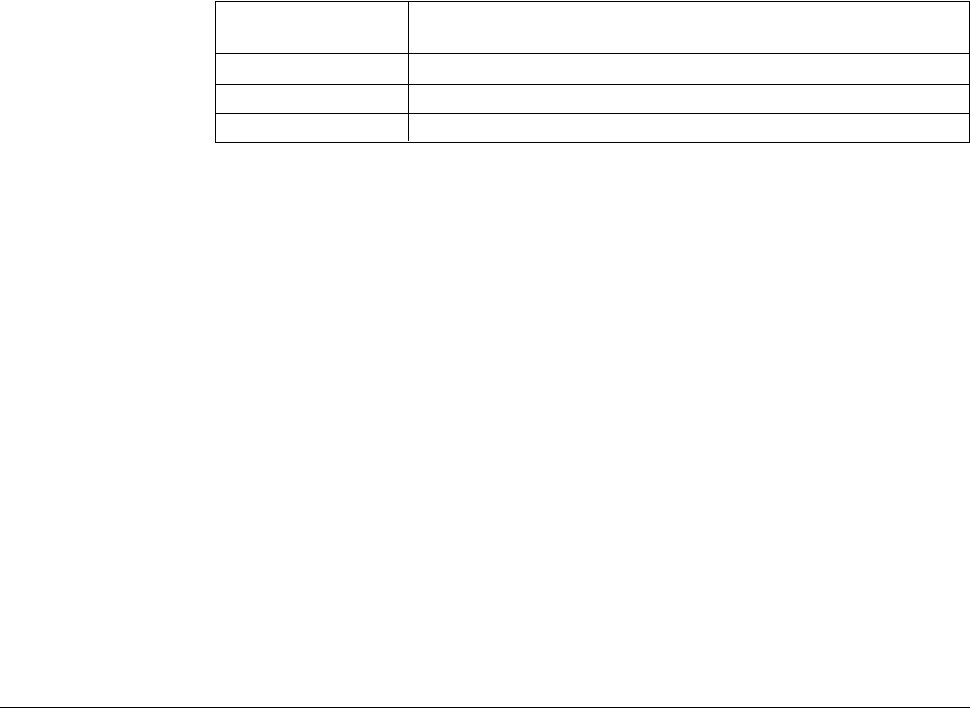
Table F.1 – Analog Input Conversion Scaling for Speed or Trim Reference
• The maximum positive analog input value (+10 VDC or 20 mA) corresponds to
the value specified as the maximum speed of the drive (P.004).
• The maximum negative analog input value (-10 VDC) corresponds to -P.004
(reverse or 0, see P.027).
• The minimum analog input value (0 VDC or 0 mA; 4 mA if P.011 = 4, 5, or 8-11)
corresponds to the value specified as the minimum speed of the drive (P.003).
• When P.011 = 0 or 1, there is no hysteresis provided around zero on the input.
Therefore, if the input fluctuates around zero, the reference will toggle between
positive minimum speed (+P.003) and negative minimum speed (-P.003).
Note that the analog input is scaled based on the values entered in P.003 and
P.004. If these parameters are changed while the drive is running, and the analog
input is used as the speed or trim reference, the speed reference will change even
though the input value has not.