
Software Start-Up and Ref. Owner manual
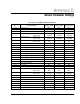
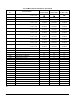
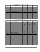
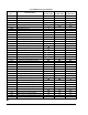

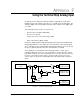
Table Of Contents
- GV3000/SE AC General Purpose (V/Hz) and Vector Duty Drive, 1 - 20 HP, 230V AC Software Start-Up and Reference Manual D2-3387-5
- Important User Information
- Document Update
- Summary of Changes
- Table of Contents
- List of Figures
- List of Tables
- Preface
- Chapter 1 - Starting Up the Drive for Volts/Hertz Regulation
- Chapter 2 - Starting Up the Drive for Vector Regulation
- Chapter 3 - Using the Keypad/Display To Program, Monitor, and Control the Drive
- Chapter 4 - Programming Reference
- Chapter 5 - Troubleshooting the Drive Using Error Codes
- Appendix A - Alphabetical Listing of Parameters
- Appendix B - Record of User Parameter Settings
- Appendix C - Power Module-Dependent Parameter Default Values (230 V Series)
- Appendix D - Default Parameter Settings
- Appendix E - Configuring the Digital Inputs When the RMI Board Is Installed in the Drive
- Appendix F - Using the Terminal Strip Analog Input
- Appendix G - Drive Regulation Overview
- Back Cover / Publication D2-3387-5 July 2013
F-1
Using the Terminal Strip Analog Input
An analog reference input is provided at terminals 12 through 15 on the drive's
Regulator board. This input accepts either a +/–10 VDC or 0 to 20 mA signal. The
analog-to-digital conversion provides 10-bit plus sign resolution and a digital range
of +/–1023.
The analog input can be used as a reference for:
• Speed reference (P.000, P.007/P.008)
• Trim reference (P.014)
• Torque reference (vector control only) (U.000)
• Outer control loop feedback (U.040)
Parameters P.009 (Terminal Strip Analog Input Offset) and P.010 (Terminal Strip
Analog Input Gain) are used to adjust the converted value for any external signal
errors. Parameter P.011 (Terminal Strip Analog Input Configure) is used to specify
the type of signal used and to invert the converted value, if required.
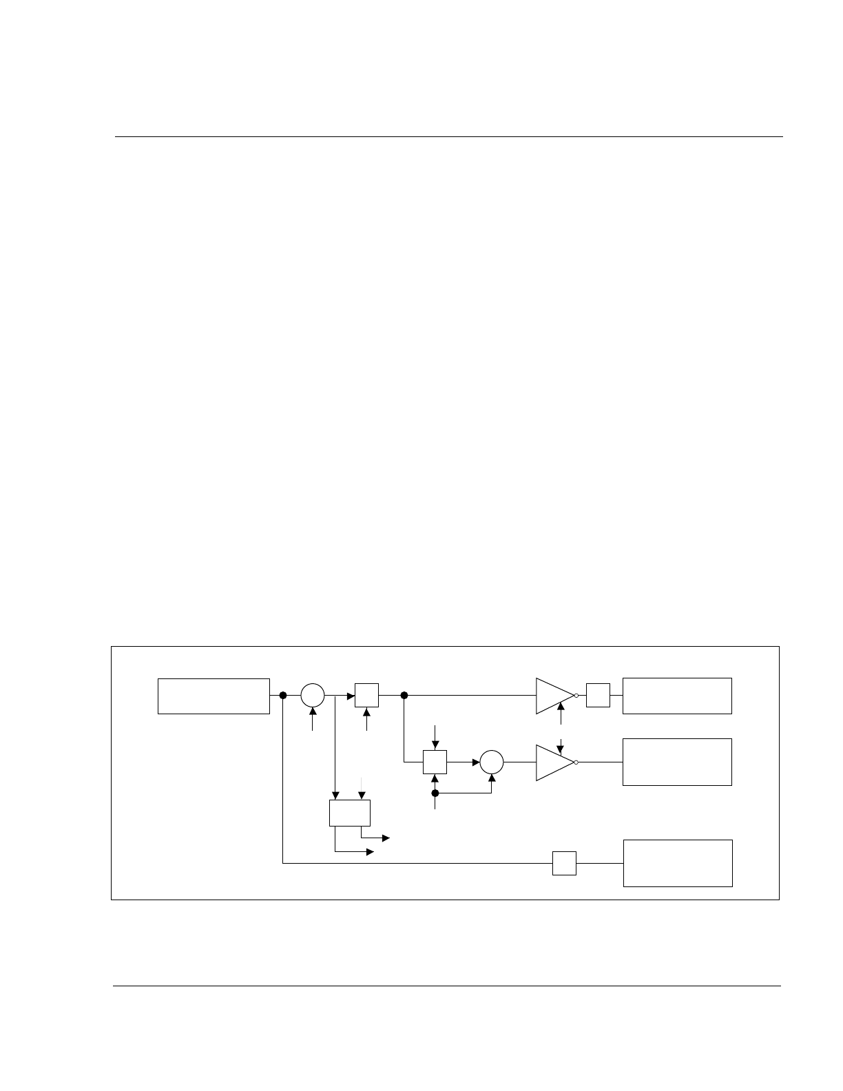
Three quantities are calculated from the analog input value: scaled, speed
normalized, and torque reference. The scaled value is used for the outer control
loop (OCL) feedback. The speed normalized value is used for either speed or trim
reference. The torque reference value is used for torque reference for vector
control. Figure F.1 shows the relationship between the input and the calculated
values.
APPENDIX F
Using the Terminal Strip Analog Input
Figure F.1 – Terminal Strip Analog Input
Analog Input
(+/- 1023)
Loss
Detect
P.009 P.010
P.011
P.004
P.003
G
G
+
+
+
+
P.011
x4
x4
Analog Input Scaled
4095 @ 10V (20 mA)
Analog Input
Normalized to Speed
P.004 @ 10V (20 mA)
Analog Input Torque
Reference
150% iq @ 10V (20 mA)
Aln Alarm
Aln Fault