
Software Start-Up and Ref. Owner manual
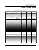
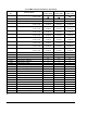
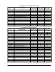
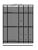
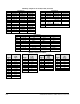

Table Of Contents
- GV3000/SE AC General Purpose (V/Hz) and Vector Duty Drive, 1 - 20 HP, 230V AC Software Start-Up and Reference Manual D2-3387-5
- Important User Information
- Document Update
- Summary of Changes
- Table of Contents
- List of Figures
- List of Tables
- Preface
- Chapter 1 - Starting Up the Drive for Volts/Hertz Regulation
- Chapter 2 - Starting Up the Drive for Vector Regulation
- Chapter 3 - Using the Keypad/Display To Program, Monitor, and Control the Drive
- Chapter 4 - Programming Reference
- Chapter 5 - Troubleshooting the Drive Using Error Codes
- Appendix A - Alphabetical Listing of Parameters
- Appendix B - Record of User Parameter Settings
- Appendix C - Power Module-Dependent Parameter Default Values (230 V Series)
- Appendix D - Default Parameter Settings
- Appendix E - Configuring the Digital Inputs When the RMI Board Is Installed in the Drive
- Appendix F - Using the Terminal Strip Analog Input
- Appendix G - Drive Regulation Overview
- Back Cover / Publication D2-3387-5 July 2013

E-3
Configuring the Digital Inputs When the RMI Board Is Installed in the Drive
Example 1
Functions to be assigned to Regulator board terminal strip:
• 2 preset speeds
• TRQ/SPD
• FWD/REV
Function to be assigned to RMI terminal strip:
• MOP
To configure the Regulator board digital inputs for the above functions, P.007
should be set to 10, and P.008 should be set to 2. Using the Option Comparison
Tables, a setting in P.007 of 10 allows P.008 to be set to 2.
To configure the RMI terminal strip for the MOP function, r.030 should be set to 2.
Using the Option Comparison Tables, this setting is acceptable if P.008 is set to 2.
Therefore, these functions can be easily accommodated by the four digital inputs
by setting P.007 = 10, P.008 = 2, and r.030 = 2.
Example 2
Functions to be assigned to the Regulator board terminal strip:
• 4 preset speeds
• TRQ/SPD
• FWD/REV
Function to be assigned to the RMI terminal strip:
• MOP
To configure the Regulator board digital inputs for the above functions, P.007
should be set to 10, and P.008 should be set to 3. Using the Option Comparison
Tables, a setting of 10 in P.007 does not allow a setting of 3 for P.008. This is
because the parameter settings both require the use of digital inputs 7 (the TRQ/
SPD and FWD/REV functions use digital inputs 7 and 8; the four presets use
digital inputs 6 and 7).
In this case, the function to be assigned to the Regulator board terminal strip
need to be re-assessed (for example, reduce the number of preset speeds to 2).