
Software Start-Up and Ref. Owner manual
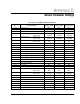
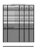
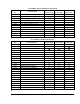
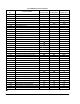
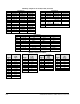

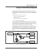
Table Of Contents
- GV3000/SE AC General Purpose (V/Hz) and Vector Duty Drive, 1 - 20 HP, 230V AC Software Start-Up and Reference Manual D2-3387-5
- Important User Information
- Document Update
- Summary of Changes
- Table of Contents
- List of Figures
- List of Tables
- Preface
- Chapter 1 - Starting Up the Drive for Volts/Hertz Regulation
- Chapter 2 - Starting Up the Drive for Vector Regulation
- Chapter 3 - Using the Keypad/Display To Program, Monitor, and Control the Drive
- Chapter 4 - Programming Reference
- Chapter 5 - Troubleshooting the Drive Using Error Codes
- Appendix A - Alphabetical Listing of Parameters
- Appendix B - Record of User Parameter Settings
- Appendix C - Power Module-Dependent Parameter Default Values (230 V Series)
- Appendix D - Default Parameter Settings
- Appendix E - Configuring the Digital Inputs When the RMI Board Is Installed in the Drive
- Appendix F - Using the Terminal Strip Analog Input
- Appendix G - Drive Regulation Overview
- Back Cover / Publication D2-3387-5 July 2013

E-1
Configuring the Digital Inputs When the RMI Board Is Installed in the Drive
APPENDIX E
Configuring the Digital Inputs
When the RMI Board Is
Installed in the Drive
The GV3000/SE Regulator board contains three user-configurable digital inputs.
Parameter P.007 (Terminal Strip Digital Inputs Configure) and P.008 (Terminal Strip
Speed Reference Source) are used to specify how these digital inputs are used.
If an optional Remote Meter Interface (RMI) board is installed in the drive, four
additional digital inputs are available. RMI parameter r.030 is used to specify how
the RMI digital inputs are used.
The Regulator board digital inputs and the RMI digital inputs are not permitted to be
used for the same functions. One parameter cannot be set to a value which requires
resources (digital inputs) or a duplication of function which is used or defined by the
value of another parameter.
The acceptable values for P.008 are based on the value selected for P.007 and by
the value selected for r.030:
• P.008 is limited by P.007 and r.030
• P.007 is limited by P.008
• r.030 is limited by P.008
First determine what functions are to be assigned to the three digital inputs on the
Regulator board. Once you have determined this, select the appropriate settings for
P.007 and P.008. As shown in the following tables, the desired value for P.008
must be permissible by both the P.007 and r.030 values. If either column
indicates the value is not acceptable, then P.008 cannot be set to that value. Use
the following tables to help determine the appropriate settings for your application.
Refer to chapter 4 in this manual for a complete description of parameters P.007
and P.008 and their corresponding options. Refer to the RMI board instruction
manual (D2-3341) for a complete description of parameter r.030 and its options.