
Software Start-Up and Ref. Owner manual
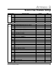
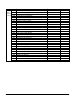
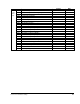
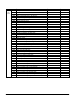
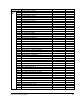

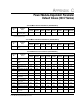

Table Of Contents
- GV3000/SE AC General Purpose (V/Hz) and Vector Duty Drive, 1 - 20 HP, 230V AC Software Start-Up and Reference Manual D2-3387-5
- Important User Information
- Document Update
- Summary of Changes
- Table of Contents
- List of Figures
- List of Tables
- Preface
- Chapter 1 - Starting Up the Drive for Volts/Hertz Regulation
- Chapter 2 - Starting Up the Drive for Vector Regulation
- Chapter 3 - Using the Keypad/Display To Program, Monitor, and Control the Drive
- Chapter 4 - Programming Reference
- Chapter 5 - Troubleshooting the Drive Using Error Codes
- Appendix A - Alphabetical Listing of Parameters
- Appendix B - Record of User Parameter Settings
- Appendix C - Power Module-Dependent Parameter Default Values (230 V Series)
- Appendix D - Default Parameter Settings
- Appendix E - Configuring the Digital Inputs When the RMI Board Is Installed in the Drive
- Appendix F - Using the Terminal Strip Analog Input
- Appendix G - Drive Regulation Overview
- Back Cover / Publication D2-3387-5 July 2013
B-5
Record of User Parameter Settings
Parameter No.
Setting
Date
Second
Menu
RMI
r.001
r.002
r.003
r.004
r.005
r.006
r.007
r.008
r.009
r.010
r.011
r.014
r.015
r.016
r.020
r.021
r.022
r.025
r.030
r.031
r.032
r.033
r.034
r.035
r.036
r.037
r.040
r.041
r.042
r.043
r.044
r.045
r.046
r.050
r.051
r.052
r.053
r.056
r.057
r.058
r.059
r.060
r.063
r.064
r.065
r.066
Parameter Name
Analog Output 1 Source
Analog Output 1 Offset
Analog Output 1 Gain
Analog Output 2 Source
Analog Output 2 Offset
Analog Output 2 Gain
Analog Output 3 Source
Analog Output 3 Offset
Analog Output 3 Gain
Analog Input Offset
Analog Input Gain
Frequency Input Sample Period
Frequency Input Offset
Frequency Input Gain
PI Regulator Offset
PI Regulator Proportion Gain
PI Regulator Integral Gain
Torque/Current Limit Source
Digital Input Configuration
Digital Output 1 Configuration
Digital Output 2 Configuration
Digital Output 3 Configuration
Digital Output 4 Configuration
Relay Output 1 (NO) Configuration
Relay Output 2 (NO/NC) Configuration
Relay Output 3 (NO/NC) Configuration
Digital Output 1 Delay Time
Digital Output 2 Delay Time
Digital Output 3 Delay Time
Digital Output 4 Delay Time
Relay Output 1 Delay Time
Relay Output 2 Delay Time
Relay Output 3 Delay Time
Speed Detection Level 1
Speed Detection Level 2
Speed Detection Level 3
Speed Detection Hysteresis Band
Low Speed Detection Level
Current Detection Level 1
Current Detection Level 2
Current Detection Level 3
Current Detection Hysteresis
Torque Detection Level 1
Torque Detection Level 2
Torque Detection Level 3
Torque Detection Hysteresis