
Software Start-Up and Ref. Owner manual
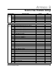
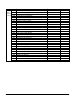

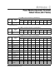

Table Of Contents
- GV3000/SE AC General Purpose (V/Hz) and Vector Duty Drive, 1 - 20 HP, 230V AC Software Start-Up and Reference Manual D2-3387-5
- Important User Information
- Document Update
- Summary of Changes
- Table of Contents
- List of Figures
- List of Tables
- Preface
- Chapter 1 - Starting Up the Drive for Volts/Hertz Regulation
- Chapter 2 - Starting Up the Drive for Vector Regulation
- Chapter 3 - Using the Keypad/Display To Program, Monitor, and Control the Drive
- Chapter 4 - Programming Reference
- Chapter 5 - Troubleshooting the Drive Using Error Codes
- Appendix A - Alphabetical Listing of Parameters
- Appendix B - Record of User Parameter Settings
- Appendix C - Power Module-Dependent Parameter Default Values (230 V Series)
- Appendix D - Default Parameter Settings
- Appendix E - Configuring the Digital Inputs When the RMI Board Is Installed in the Drive
- Appendix F - Using the Terminal Strip Analog Input
- Appendix G - Drive Regulation Overview
- Back Cover / Publication D2-3387-5 July 2013

A-4
GV3000/SE 230 VAC Drive, Software Reference Version 6.04
Second Menu RMI Parameters
(continued)
Digital Output 1 Configuration........................................................................... r.031
Digital Output 1 Delay Time .............................................................................. r.040
Digital Output 2 Configuration........................................................................... r.032
Digital Output 2 Delay Time .............................................................................. r.041
Digital Output 3 Configuration........................................................................... r.033
Digital Output 3 Delay Time .............................................................................. r.042
Digital Output 4 Configuration........................................................................... r.034
Digital Output 4 Delay Time .............................................................................. r.043
Frequency Input Gain ....................................................................................... r.016
Frequency Input Offset ..................................................................................... r.015
Frequency Input Sample Period ....................................................................... r.014
Low Speed Detection Level .............................................................................. r.056
PI Regulator Integral Gain ................................................................................ r.022
PI Regulator Offset ........................................................................................... r.020
PI Regulator Proportional Gain ......................................................................... r.021
Relay Output 1 (NO) Configuration................................................................... r.035
Relay Output 1 Delay Time ............................................................................... r.044
Relay Output 2 (NO/NC) Configuration ............................................................ r.036
Relay Output 2 Delay Time ............................................................................... r.045
Relay Output 3 (NO/NC) Configuration ............................................................ r.037
Relay Output 3 Delay Time ............................................................................... r.046
Speed Detection Hysteresis Band .................................................................... r.053
Speed Detection Level 1 ................................................................................... r.050
Speed Detection Level 2 ................................................................................... r.051
Speed Detection Level 3 ................................................................................... r.052
Torque Detection Hysteresis............................................................................. r.066
Torque Detection Level 1 .................................................................................. r.063
Torque Detection Level 2 .................................................................................. r.064
Torque Detection Level 3 .................................................................................. r.065
Torque/Current Limit Source............................................................................. r.025
Refer to the Remote Meter Interface board manual (D2-3341) for the RMI parameter
descriptions.