
Software Start-Up and Ref. Owner manual
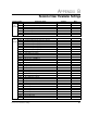
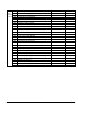


Table Of Contents
- GV3000/SE AC General Purpose (V/Hz) and Vector Duty Drive, 1 - 20 HP, 230V AC Software Start-Up and Reference Manual D2-3387-5
- Important User Information
- Document Update
- Summary of Changes
- Table of Contents
- List of Figures
- List of Tables
- Preface
- Chapter 1 - Starting Up the Drive for Volts/Hertz Regulation
- Chapter 2 - Starting Up the Drive for Vector Regulation
- Chapter 3 - Using the Keypad/Display To Program, Monitor, and Control the Drive
- Chapter 4 - Programming Reference
- Chapter 5 - Troubleshooting the Drive Using Error Codes
- Appendix A - Alphabetical Listing of Parameters
- Appendix B - Record of User Parameter Settings
- Appendix C - Power Module-Dependent Parameter Default Values (230 V Series)
- Appendix D - Default Parameter Settings
- Appendix E - Configuring the Digital Inputs When the RMI Board Is Installed in the Drive
- Appendix F - Using the Terminal Strip Analog Input
- Appendix G - Drive Regulation Overview
- Back Cover / Publication D2-3387-5 July 2013

A-3
Alphabetical Listing of Parameters
Second Menu Vector Parameters
AC Line Volts .................................................................................................... U.018
Current Compounding Gain .............................................................................. U.026
Encoder PPR .................................................................................................... U.001
Field Weakening Start RPM.............................................................................. U.016
Flux Current Regulator Integral Gain ................................................................ U.020
Flux Current Regulator Proportional Gain ........................................................ U.019
High DC Bus Fault Avoidance Enable .............................................................. U.024
Inertia Compensation Gain ............................................................................... U.027
Losses Compensation Gain .............................................................................. U.028
Low DC Bus Fault Avoidance Enable ............................................................... U.023
Magnetizing Current.......................................................................................... U.006
Motor Nameplate Amps .................................................................................... U.004
Motor Nameplate Base Frequency ................................................................... U.003
Motor Nameplate Horsepower .......................................................................... U.022
Motor Nameplate RPM ..................................................................................... U.005
Motor Nameplate Volts ..................................................................................... U.007
Motor Poles ....................................................................................................... U.002
Motor Top Speed .............................................................................................. U.017
Outer Control Loop Feedback Select ............................................................... U.040
Outer Control Loop Integral Gain...................................................................... U.046
Outer Control Loop Lead/Lag Low Frequency ................................................. U.042
Outer Control Loop Lead/Lag Ratio .................................................................. U.043
Outer Control Loop Lead/Lag Select ................................................................ U.041
Outer Control Loop Proportional Gain .............................................................. U.045
Outer Control Loop Proportional Trim Enable .................................................. U.048
Outer Control Loop Reference Gain ................................................................. U.044
Outer Control Loop Trim Range Percentage .................................................... U.047
Rotor Time Constant ......................................................................................... U.021
Speed Regulator Integral Gain ......................................................................... U.013
Speed Regulator Proportional Gain .................................................................. U.012
SVC Slip Adjust ................................................................................................. U.030
SVC Sync Direction .......................................................................................... U.031
SVC Flux Current Regulator Gain .................................................................... U.032
Torque Reference Source................................................................................. U.000
Torque Regulator Integral Gain ........................................................................ U.015
Torque Regulator Proportional Gain ................................................................. U.014
Torque Self-Tune Enable .................................................................................. U.008
Torque Self-Tune Result ................................................................................... U.009
Zero Speed Hold Time ...................................................................................... U.025
Second Menu RMI Parameters
Analog Input Gain ............................................................................................. r.011
Analog Input Offset ........................................................................................... r.010
Analog Output 1 Gain ....................................................................................... r.003
Analog Output 1 Offset ..................................................................................... r.002
Analog Output 1 Source.................................................................................... r.001
Analog Output 2 Gain ....................................................................................... r.006
Analog Output 2 Offset ..................................................................................... r.005
Analog Output 2 Source.................................................................................... r.004
Analog Output 3 Gain ....................................................................................... r.009
Analog Output 3 Offset ..................................................................................... r.008
Analog Output 3 Source.................................................................................... r.007
Current Detection Hysteresis ............................................................................ r.060
Current Detection Level 1 ................................................................................. r.057
Current Detection Level 2 ................................................................................. r.058
Current Detection Level 3 ................................................................................. r.059
Digital Input Configuration ................................................................................ r.030