Software Start-Up and Ref. Owner manual
Table Of Contents
- GV3000/SE AC General Purpose (V/Hz) and Vector Duty Drive, 1 - 20 HP, 230V AC Software Start-Up and Reference Manual D2-3387-5
- Important User Information
- Document Update
- Summary of Changes
- Table of Contents
- List of Figures
- List of Tables
- Preface
- Chapter 1 - Starting Up the Drive for Volts/Hertz Regulation
- Chapter 2 - Starting Up the Drive for Vector Regulation
- Chapter 3 - Using the Keypad/Display To Program, Monitor, and Control the Drive
- Chapter 4 - Programming Reference
- Chapter 5 - Troubleshooting the Drive Using Error Codes
- Appendix A - Alphabetical Listing of Parameters
- Appendix B - Record of User Parameter Settings
- Appendix C - Power Module-Dependent Parameter Default Values (230 V Series)
- Appendix D - Default Parameter Settings
- Appendix E - Configuring the Digital Inputs When the RMI Board Is Installed in the Drive
- Appendix F - Using the Terminal Strip Analog Input
- Appendix G - Drive Regulation Overview
- Back Cover / Publication D2-3387-5 July 2013

4-92
GV3000/SE 230 VAC Drive, Software Reference Version 6.04
This parameter
enables the gain
block on the output
of the outer control
loop PI block.
Parameter Range: OFF = Disable proportional trim
ON = Enable proportional trim
Default Setting: OFF
Parameter Type: Configurable
Refer also to parameters: U.040 Outer Control Loop Feedback Source
U.041 Outer Control Loop Lead/Lag Select
U.042 Outer Control Loop Lead/Lag Low Frequency
U.043 Outer Control Loop Lead/Lag Ratio
U.044 Outer Control Loop Reference Gain
U.045 Outer Control Loop Proportional Gain
U.046 Outer Control Loop Integral Gain
U.047 Outer Control Loop Trim Range Percentage
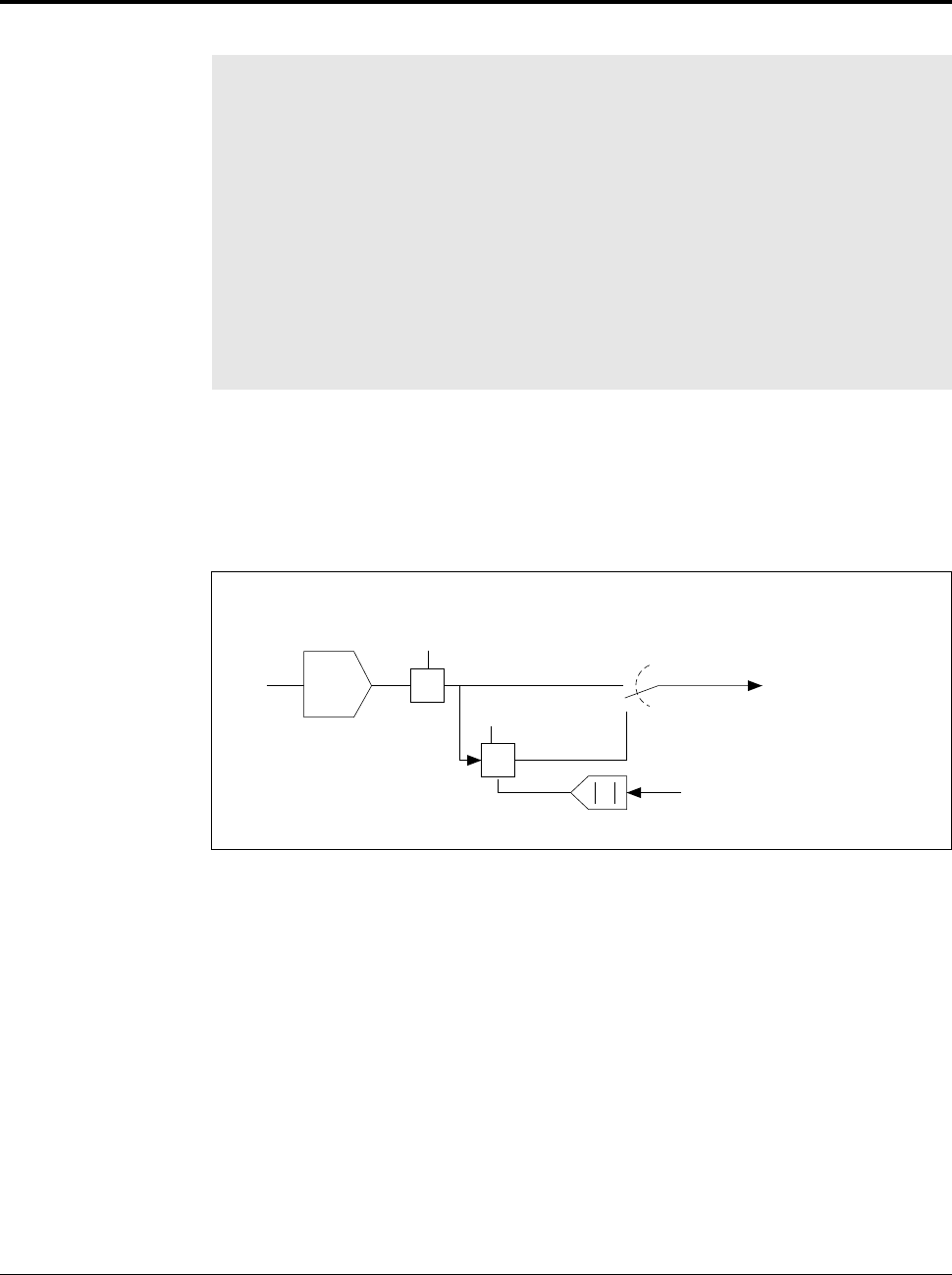
If U.048 = ON, a gain block scales the outer control loop output proportional to the
speed reference signal at the output of the S/Ramp block (normalized to top speed).
See figure 4.15. See Appendix G for the complete outer control loop block diagram.
This parameter limits the control the outer control loop has on the speed reference
during line start.
U.048 Outer Control Loop Proportional Trim Enable
Figure 4.15 – Outer Control Loop Proportional Trim
PI
G
G
x
OCL trim range
(U.047)
OCL Prop Trim
Enable (U.048)
OCL output (to
speed loop block
diagram, see
Appendix G)
Speed ref S-curve
block output
Top_spd
Div
Mult
Off
On
Rst


