
Software Start-Up and Ref. Owner manual
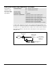
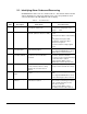
Table Of Contents
- GV3000/SE AC General Purpose (V/Hz) and Vector Duty Drive, 1 - 20 HP, 230V AC Software Start-Up and Reference Manual D2-3387-5
- Important User Information
- Document Update
- Summary of Changes
- Table of Contents
- List of Figures
- List of Tables
- Preface
- Chapter 1 - Starting Up the Drive for Volts/Hertz Regulation
- Chapter 2 - Starting Up the Drive for Vector Regulation
- Chapter 3 - Using the Keypad/Display To Program, Monitor, and Control the Drive
- Chapter 4 - Programming Reference
- Chapter 5 - Troubleshooting the Drive Using Error Codes
- Appendix A - Alphabetical Listing of Parameters
- Appendix B - Record of User Parameter Settings
- Appendix C - Power Module-Dependent Parameter Default Values (230 V Series)
- Appendix D - Default Parameter Settings
- Appendix E - Configuring the Digital Inputs When the RMI Board Is Installed in the Drive
- Appendix F - Using the Terminal Strip Analog Input
- Appendix G - Drive Regulation Overview
- Back Cover / Publication D2-3387-5 July 2013

4-86
GV3000/SE 230 VAC Drive, Software Reference Version 6.04
U.028 Losses Compensation Gain
This parameter
specifies the gain
applied to the speed
loop reference signal
to generate the
losses compensation
signal. The result is
added to the speed
PI output to produce
the torque reference
signal.
Parameter Range: 0.0 to 1.000
Default Setting: 0.0 (Disable losses compensation)
Parameter Type: Tunable
Refer also to parameters: U.026 Current Compounding Gain
U.027 Inertia Compensation Gain
Losses compensation is the scaled output of the speed loop S/Ramp block (speed
reference). It is added to the speed loop output and the inertia compensation signal
to produce the final torque reference.
Refer to the speed loop block diagram in Appendix G.
U.030 SVC Slip Adjust
Parameter Range: 0.50 to 1.50
Default Setting: 1.00
Parameter Type: Tunable
Refer also to parameters: N/A
For SVC operation, in the absence of a speed feedback device, operation of the
speed loop is based on an estimated speed feedback. Estimated speed feedback is
based on knowing the slip of the motor, which changes with motor temperature.
This parameter is provided to accommodate various operating conditions.
For a cold motor, the typical value should be 0.80. For a hot motor, the value
should be 1.0.
This parameter
adjusts the slip
compensation to
match the operating
temperature of the
motor.
This feature applies
to SVC operation
only.