
Software Start-Up and Ref. Owner manual
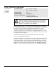
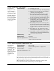
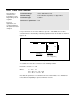
Table Of Contents
- GV3000/SE AC General Purpose (V/Hz) and Vector Duty Drive, 1 - 20 HP, 230V AC Software Start-Up and Reference Manual D2-3387-5
- Important User Information
- Document Update
- Summary of Changes
- Table of Contents
- List of Figures
- List of Tables
- Preface
- Chapter 1 - Starting Up the Drive for Volts/Hertz Regulation
- Chapter 2 - Starting Up the Drive for Vector Regulation
- Chapter 3 - Using the Keypad/Display To Program, Monitor, and Control the Drive
- Chapter 4 - Programming Reference
- Chapter 5 - Troubleshooting the Drive Using Error Codes
- Appendix A - Alphabetical Listing of Parameters
- Appendix B - Record of User Parameter Settings
- Appendix C - Power Module-Dependent Parameter Default Values (230 V Series)
- Appendix D - Default Parameter Settings
- Appendix E - Configuring the Digital Inputs When the RMI Board Is Installed in the Drive
- Appendix F - Using the Terminal Strip Analog Input
- Appendix G - Drive Regulation Overview
- Back Cover / Publication D2-3387-5 July 2013
4-84
GV3000/SE 230 VAC Drive, Software Reference Version 6.04
U.024 High DC Bus Avoidance Enable
This parameter
selects how the drive
responds to high bus
voltage.
This feature is not
available if the drive
is configured as a
torque regulator.
Parameter Range: OFF = Drive will not attempt to regulate the DC bus
on a high bus condition
ON = Drive will attempt to regulate the DC bus on a
high bus condition
Default Setting: OFF
Parameter Type: Tunable
Refer also to parameters: P.002 Decel Time 1
P.018 Decel Time 2
If DC bus voltage exceeds a predetermined threshold, the drive generates a high
bus alarm (HIdc). If U.024 = ON, the drive attempts to regulate the bus to avoid a
high bus fault (HU). Note that this may extend the programmed deceleration time
(P.002, P.018). See table 5.1 in chapter 5 for the alarm thresholds.
Set this parameter to OFF if a dynamic braking unit is connected to the drive.
For SVC operation, drive speed may increase as much as 5% above the speed
reference in an attempt to decrease the DC bus voltage level.
U.025 Zero Speed Hold Time
This parameter
selects the amount of
time for which zero
speed is held at the
end of ramp stop
sequence.
Parameter Range: 0.0 to 20.0 seconds
Default Setting: 0.0
Parameter Type: Tunable
Refer also to parameters: N/A
ATTENTION: The motor is energized when the drive is operating at
zero speed. The user is responsible for ensuring safe conditions for
operating personnel by providing suitable guards, audible or visual
alarms, or other devices to indicate that the drive is operating at zero
speed. Failure to observe this precaution could result in severe bodily
injury or loss of life.
This feature provides the capability to hold the motor at zero speed at the end of a
ramp stop for a user-specified amount of time (U.025). During the zero speed hold
time period, the running indicator remains on.
For FVC operation, a zero speed reference is applied for the time specified in
U.025, regulating torque based on load. Note that this will override the Minimum
Speed setting (P.003).
For SVC operation, magnetizing current is applied for the time specified in U.025.
!