
Software Start-Up and Ref. Owner manual
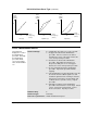
Table Of Contents
- GV3000/SE AC General Purpose (V/Hz) and Vector Duty Drive, 1 - 20 HP, 230V AC Software Start-Up and Reference Manual D2-3387-5
- Important User Information
- Document Update
- Summary of Changes
- Table of Contents
- List of Figures
- List of Tables
- Preface
- Chapter 1 - Starting Up the Drive for Volts/Hertz Regulation
- Chapter 2 - Starting Up the Drive for Vector Regulation
- Chapter 3 - Using the Keypad/Display To Program, Monitor, and Control the Drive
- Chapter 4 - Programming Reference
- Chapter 5 - Troubleshooting the Drive Using Error Codes
- Appendix A - Alphabetical Listing of Parameters
- Appendix B - Record of User Parameter Settings
- Appendix C - Power Module-Dependent Parameter Default Values (230 V Series)
- Appendix D - Default Parameter Settings
- Appendix E - Configuring the Digital Inputs When the RMI Board Is Installed in the Drive
- Appendix F - Using the Terminal Strip Analog Input
- Appendix G - Drive Regulation Overview
- Back Cover / Publication D2-3387-5 July 2013
4-68
GV3000/SE 230 VAC Drive, Software Reference Version 6.04
H.020 Identification Request
This parameter
enables the
procedure that
identifies Power
Module and motor
characteristics.
Parameter Range: OFF = Disable identification procedure
ON = Enable identification procedure
Default Setting: OFF
Parameter Type: Configurable
Refer also to parameters: P.005 Current Limit
P.047 Carrier Frequency (kHz)
P.095 Power Module Output Amps
H.002 Motor Nameplate Amps
H.019 Identification Result
ATTENTION: The motor shaft can rotate in either direction by up to
one (1) revolution, providing minimum torque immediately after the
identification procedure has been started. Stay clear of rotating
machinery. Failure to observe this precaution could result in bodily injury.
ATTENTION: Carrier Frequency (P.047) and Current Limit (P.005)
must be set correctly before activating the identification procedure to
avoid motor overloading and/or overheating. Failure to observe this
precaution could result in damage to, or destruction of, the equipment.
ATTENTION: The motor can rotate in the reverse direction even if
reverse disable has been selected in P.027. Uncouple the motor from
any driven machinery that could be damaged by reverse rotation.
Failure to observe this precaution could result in damage to, or
destruction of, the equipment.
Before starting this procedure, verify that the motor is at rest and connected to the
drive. The motor can be connected to the driven machinery. Verify that Motor
Nameplate Volts (H.000), Carrier Frequency (P.047), and Current Limit (P.005) are
set correctly.
The identification procedure should be run only in the following cases:
• after the initial assembly of the inverter (performed at Reliance Electric)
• if H.003 (Torque Boost Voltage) = 0
The ratio of maximum Power Module Output Amps (P.095) to Motor Nameplate
Amps (H.002) should not be greater than 3:1. (Maximum Power Module Output
Amps is dependent on Power Module size and the selected Carrier Frequency
(P.047)). Compare the value of P.095 to H.002 to decide on the adjustment of
Current Limit (P.005) to avoid motor damage.
Do not connect a motor that cannot withstand maximum Power Module Output
Amps reduced by selected Current Limit (P.005).
Note that the identification procedure must not be performed when more than one
motor is being driven by the inverter.
!