
Software Start-Up and Ref. Owner manual
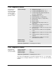
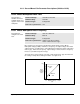
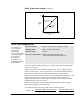
Table Of Contents
- GV3000/SE AC General Purpose (V/Hz) and Vector Duty Drive, 1 - 20 HP, 230V AC Software Start-Up and Reference Manual D2-3387-5
- Important User Information
- Document Update
- Summary of Changes
- Table of Contents
- List of Figures
- List of Tables
- Preface
- Chapter 1 - Starting Up the Drive for Volts/Hertz Regulation
- Chapter 2 - Starting Up the Drive for Vector Regulation
- Chapter 3 - Using the Keypad/Display To Program, Monitor, and Control the Drive
- Chapter 4 - Programming Reference
- Chapter 5 - Troubleshooting the Drive Using Error Codes
- Appendix A - Alphabetical Listing of Parameters
- Appendix B - Record of User Parameter Settings
- Appendix C - Power Module-Dependent Parameter Default Values (230 V Series)
- Appendix D - Default Parameter Settings
- Appendix E - Configuring the Digital Inputs When the RMI Board Is Installed in the Drive
- Appendix F - Using the Terminal Strip Analog Input
- Appendix G - Drive Regulation Overview
- Back Cover / Publication D2-3387-5 July 2013
4-63
Programming Reference
H.009 Avoidance Frequency Enable
(continued)
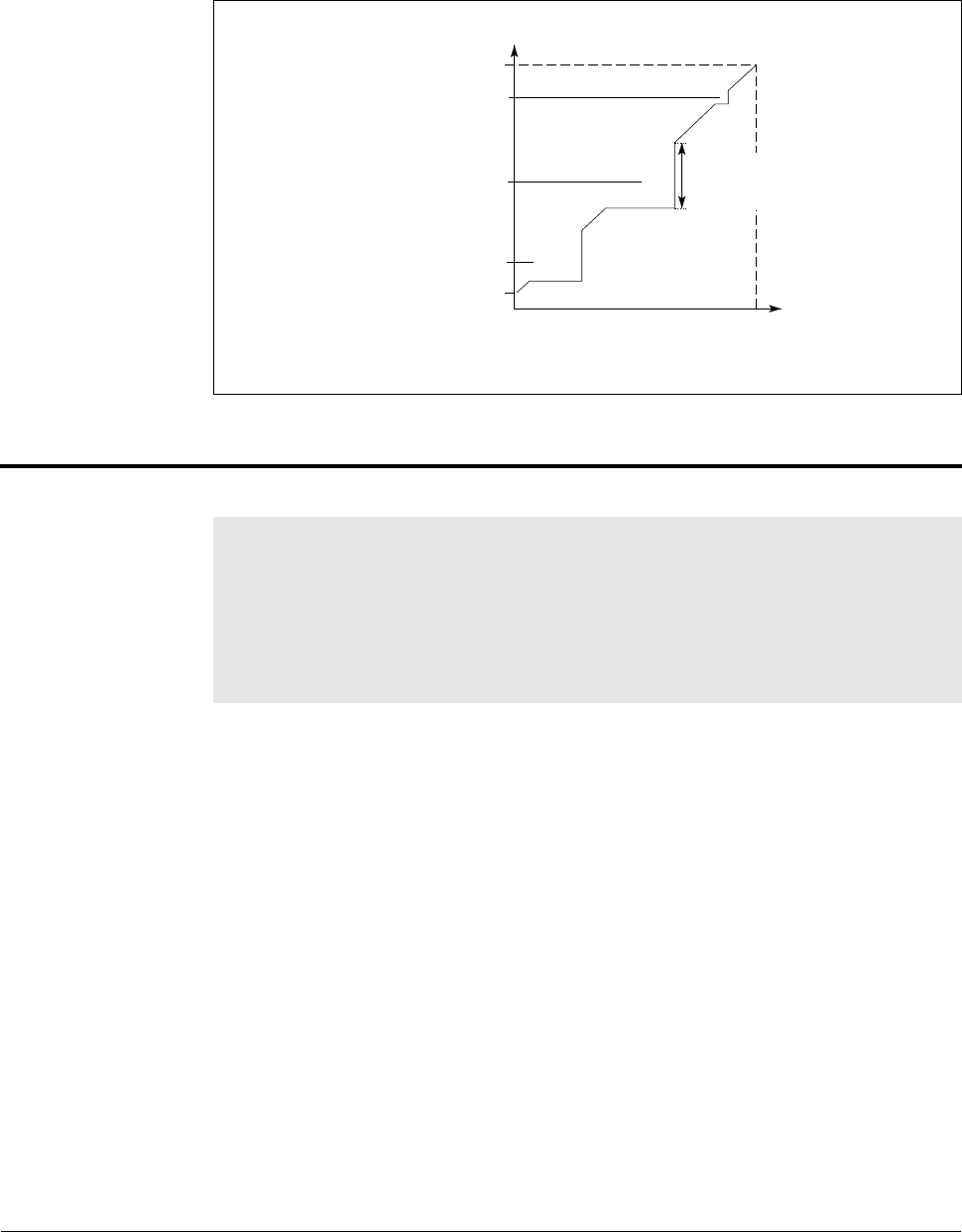
Figure 4.12 – Avoidance Frequency Band
H.010, H.012, H.014 Avoidance Frequency Midpoint 1, 2, and 3
This parameter
specifies the midpoint
of each avoidance
frequency band
selected in H.011,
H.013, and H.015.
The adjusted values may be in any order. The frequency will not be affected at
normal acceleration or deceleration but will be avoided at continuous output
frequency.
Parameter Range: 0.0 to 200.0 Hz
Default Setting: 0.0
Parameter Type: Tunable
Refer also to parameters: H.009 Avoidance Frequency Enable
H.011, H.013, H.015 Avoidance Frequency Band 1,
2, and 3
Max Hz
AF 3
AF 2
AF 1
Min Hz
Min
Max
Speed Reference
Output
Frequency
Base Frequency
Avoidance
Frequency Band