
Software Start-Up and Ref. Owner manual
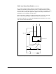
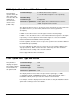
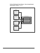
Table Of Contents
- GV3000/SE AC General Purpose (V/Hz) and Vector Duty Drive, 1 - 20 HP, 230V AC Software Start-Up and Reference Manual D2-3387-5
- Important User Information
- Document Update
- Summary of Changes
- Table of Contents
- List of Figures
- List of Tables
- Preface
- Chapter 1 - Starting Up the Drive for Volts/Hertz Regulation
- Chapter 2 - Starting Up the Drive for Vector Regulation
- Chapter 3 - Using the Keypad/Display To Program, Monitor, and Control the Drive
- Chapter 4 - Programming Reference
- Chapter 5 - Troubleshooting the Drive Using Error Codes
- Appendix A - Alphabetical Listing of Parameters
- Appendix B - Record of User Parameter Settings
- Appendix C - Power Module-Dependent Parameter Default Values (230 V Series)
- Appendix D - Default Parameter Settings
- Appendix E - Configuring the Digital Inputs When the RMI Board Is Installed in the Drive
- Appendix F - Using the Terminal Strip Analog Input
- Appendix G - Drive Regulation Overview
- Back Cover / Publication D2-3387-5 July 2013
4-54
GV3000/SE 230 VAC Drive, Software Reference Version 6.04
P.066 to P.069 Network Output Register 1 Source through Network
Output Register 4 Source
(continued)
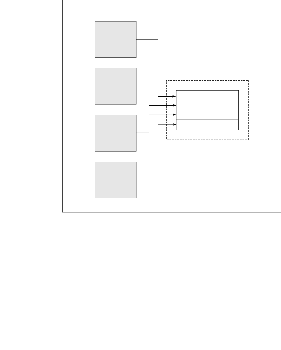
Figure 4.9 – Signal Selection for Network Output Registers
P.066
P.067
P.068
P.069
0 = Motor KW
display value
.
.
.
12
0 = Encoder
counter (x 4)
.
.
.
12
0 = Output power
factor
.
.
.
12
0 = Motor torque
display value
.
.
.
12
Network Output Register 1
Network Output Register 2
Network Output Register 3
Network Output Register 4
Network Module