
Software Start-Up and Ref. Owner manual
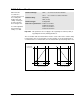
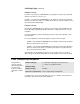
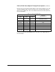
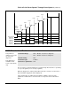
Table Of Contents
- GV3000/SE AC General Purpose (V/Hz) and Vector Duty Drive, 1 - 20 HP, 230V AC Software Start-Up and Reference Manual D2-3387-5
- Important User Information
- Document Update
- Summary of Changes
- Table of Contents
- List of Figures
- List of Tables
- Preface
- Chapter 1 - Starting Up the Drive for Volts/Hertz Regulation
- Chapter 2 - Starting Up the Drive for Vector Regulation
- Chapter 3 - Using the Keypad/Display To Program, Monitor, and Control the Drive
- Chapter 4 - Programming Reference
- Chapter 5 - Troubleshooting the Drive Using Error Codes
- Appendix A - Alphabetical Listing of Parameters
- Appendix B - Record of User Parameter Settings
- Appendix C - Power Module-Dependent Parameter Default Values (230 V Series)
- Appendix D - Default Parameter Settings
- Appendix E - Configuring the Digital Inputs When the RMI Board Is Installed in the Drive
- Appendix F - Using the Terminal Strip Analog Input
- Appendix G - Drive Regulation Overview
- Back Cover / Publication D2-3387-5 July 2013
4-33
Programming Reference
P.031 to P.038 Preset Speed 1 Through Preset Speed 8
(continued)
Each speed is selected using external switches connected to terminals 17, 18, and
19 on the Regulator board. The presets may also be selected using the Remote
Meter Interface (RMI) board. Refer to the RMI board instruction manual (D2-3341)
for more information.
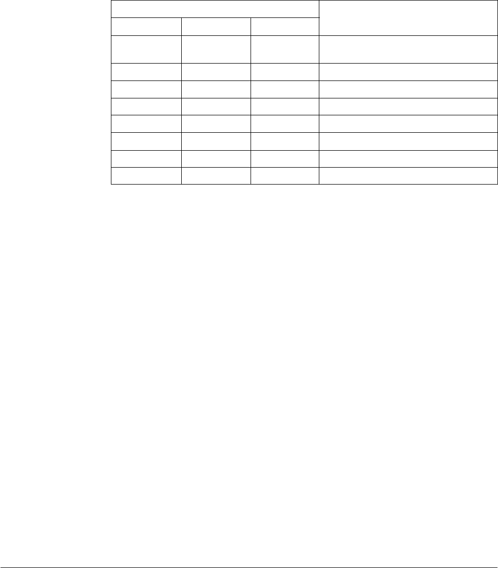
Table 4.4 – Preset Speed Digital Inputs
Digital Inputs (Terminals)
7 (18)
0 (open)
0 (open)
1 (closed)
1 (closed)
0 (open)
0 (open)
1 (closed)
1 (closed)
6 (19)
0 (open)
1 (closed)
0 (open)
1 (closed)
0 (open)
1 (closed)
0 (open)
1 (closed)
8 (17)
0 (open)
0 (open)
0 (open)
0 (open)
1 (closed)
1 (closed)
1 (closed)
1 (closed)
Selected
Speed Reference
P.031 or analog input (see P.008,
selections 5, 6, and 7)
P.032
P.033
P.034
P.035
P.036
P.037
P.038
If you have installed an optional RMI board in your drive, refer to Appendix E for
more information.