
Software Start-Up and Ref. Owner manual
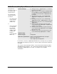
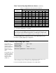
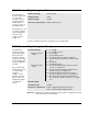
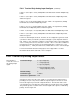
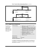
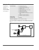
Table Of Contents
- GV3000/SE AC General Purpose (V/Hz) and Vector Duty Drive, 1 - 20 HP, 230V AC Software Start-Up and Reference Manual D2-3387-5
- Important User Information
- Document Update
- Summary of Changes
- Table of Contents
- List of Figures
- List of Tables
- Preface
- Chapter 1 - Starting Up the Drive for Volts/Hertz Regulation
- Chapter 2 - Starting Up the Drive for Vector Regulation
- Chapter 3 - Using the Keypad/Display To Program, Monitor, and Control the Drive
- Chapter 4 - Programming Reference
- Chapter 5 - Troubleshooting the Drive Using Error Codes
- Appendix A - Alphabetical Listing of Parameters
- Appendix B - Record of User Parameter Settings
- Appendix C - Power Module-Dependent Parameter Default Values (230 V Series)
- Appendix D - Default Parameter Settings
- Appendix E - Configuring the Digital Inputs When the RMI Board Is Installed in the Drive
- Appendix F - Using the Terminal Strip Analog Input
- Appendix G - Drive Regulation Overview
- Back Cover / Publication D2-3387-5 July 2013
4-21
Programming Reference
This parameter
specifies the type of
status indication
provided by the
output relay contacts
(terminal 28, 29, 30,
and 31 on the drive's
terminal strip).
Parameter Range: 0 = Output relay is energized when one or more
faults (IET) are active.
1 = Output relay is energized to show state of drive
running with 0.5 second delay added between a
start assertion and generation of motor voltage.
2 = Output relay is energized to show state of drive
running but without 0.5 second start delay.
3 = Output relay is energized when network
communication is active.
4 = Output relay is energized when all start
permissive conditions are met.
5 = Output relay is energized when one or more
alarms are active.
Default Setting: 0
Parameter Type: Configurable
Refer also to parameters: N/A
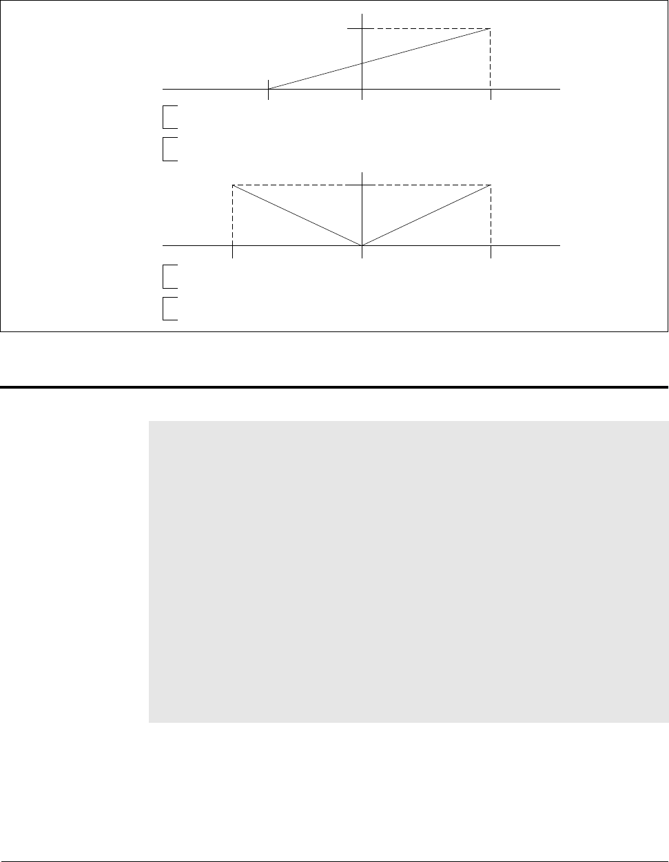
P.012 Terminal Strip Analog Output Source
(continued)
Figure 4.2 – Analog Output Selection and Scaling
P.013 Output Relay Configuration
For example, for an application using an output contactor, you can obtain a 0.5
second delay between a start assertion and the generation of motor voltage by
setting P.013 to 1. The delay will provide time for the contactor to close before
motor voltage is generated.
10V
20 mA
0V
4 mA
0
0
10V
20 mA
0V
4 mA
– Max Speed
– Top Speed
–200% Torque
–300% Torque
+Max Speed (P.004)
+Top Speed (U.017)
+200% Torque
+300% Torque
P.012 = 0
P.012 = 1
V/Hz
Vector
V/Hz
Vector
V/Hz
Vector
V/Hz
Vector
– Max Speed
– Top Speed
–200% Max Current (2 x P.095)
–300% Torque
+Max Speed (P.004)
+Top Speed (U.017)
+200% Max Currenr (2 x P.095)
+300% Torque
P.012 = 2
P.012 = 3