
Owner manual

2 Fan/Fan Transformer Replacement – Frame 6
*
PN-36158*
PN-36158
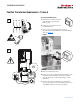
Fan Replacement - IP00, NEMA/UL
Type 1
A. Remove the two screws securing the
fan cover.
Figure 2
B. Pull-up fan enclosure and disconnect wires.
C. Remove fan assembly and replace fan.
D. Re-assemble in reverse order. Tighten all screws to
3.2 N-m (28 lb.-in.).
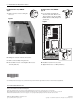
Fan Replacement - IP54, NEMA/UL
Type 12
A. Locate the Fan Assembly and
disconnect the cable. Remove the
10 screws that secure the assembly.
Pull the Fan Assembly straight out
and discard.
Figure 3
B. Install the new fan in reverse order.
C. Tighten all screws to 3.2 N-m (28 lb.-in.).
U
T1
DC-DC+BR1BR2 V
T2
W
T3
R
L1
S
L2
OUTPUT
T
L3
PE PE
USE 75C COPPER WIRE ONLY, TORQUE 52 IN-LB (6 N-M)
22-12 AWG
5.3 IN-LB
(0.6 N-M)
PS+
PS-
WIRE STRIP
x
10
Publication RA-IN010B-EN-P – November, 2008 PN-36158
Supersedes RA-IN010A-EN-P – January, 2004 Copyright © 2008 Rockwell Automation, Inc. All rights reserved. Printed in USA.
www.rockwellautomation.com
Americas: Rockwell Automation, 1201 South Second Street, Milwaukee, WI 53204 USA, Tel: (1) 414.382.2000, Fax: (1) 414.382.4444
Europe/Middle East/Africa: Rockwell Automation, Vorstlaan/Boulevard du Souverain 36, 1170 Brussels, Belgium, Tel: (32) 2 663 0600, Fax: (32) 2 663 0640
Asia Pacific: Rockwell Automation, Level 14, Core F, Cyberport 3, 100 Cyberport Road, Hong Kong, Tel: (852) 2887 4788, Fax: (852) 2508 1846
Power, Control and Information Solutions Headquarters
U.S. Allen-Bradley Drives Technical Support - Tel: (1) 262.512.8176, Fax: (1) 262.512.2222, Email: support@drives.ra.rockwell.com, Online: www.ab.com/support/abdrives