
Reference Manual Owner's manual

Publication GMLC-5.2 - November 1999
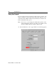
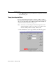
Tune Servo 105
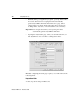
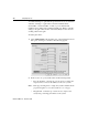
2. Make entries in the following fields:
3. In the Tuning Direction area, make entries in the following fields:
4. Make entries in the following fields:
Field Description
Tuning Travel
Limit (inches)
Type the number of units that provide a safe
travel distance given the practical travel limits
of your application.
Note: The greater the distance, the better for
tuning.
Tuning Speed Type the speed that the axis must reach during
tuning.
Tuning Output
Limit
Type a voltage output limit, as a percentage of
the value entered in the Control Output Limit
Val ue field in the Servo dialog box.
Damping Factor Type a value between 0.7 and 2.0.
Note: We recommend a default value of 0.8
to provide good gain values for most
systems.
Field Description
Positive Tune in a positive axial direction.
Negative Tune in a negative axial direction
Field Description
Positive Error
Integrator
Calculate and enter a value in the Integral Gain
field in the Gains dialog box.
Vel oc ity
Feedforward
Calculates value for the Feedforward gain field
in the Gains dialog box