
User Manual
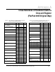

7-16
AutoMax Network Communication Option Board
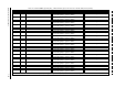
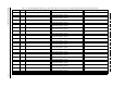
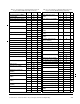
23 SPEED RAMP OUTPUT (P.199) Value of the speed reference signal immediately after the
speed loop
S-CURVE block
24
TAPER PERCENT (P.859) Percent reduction to be applied to the tension reference
from the taper function
25
TEN LOOP ERROR (P.834) Tension/current loop error signal after scaling
26
TEN PI KP OUT (P.879) Value of the tension loop pi proportional gain
27
TEN RAMP OUTPUT (P.842) Output of the tension major loop ramp block after
tension-to-current conversion
28
TEN TO CURRENT OUT (P.876) Output of the tension loop’s tension-to-current scaling
block
29 TRIM OUTPUT (P.197) Actual signal used to trim the selected speed loop
reference signal
30
UNWIND DIAMETER IN (P.828) Analog input signal (TB 16, 17) when DIAMTER/TAPER
SELECT (P.870) = DIAMETER
31 Indirect Register Status Bit-packed word containing information on
0 to 6 Offending register number. 0 = No error
7 to 12 Reserved
13 Error - Not found
14 Error - Output parameter
15 Network sync
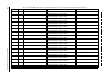
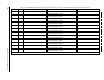
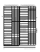
Table 7.12 – WebPak 3000 Register Map, Drop_3: Master Write Registers, FULL Connection. Tunable/Configurable Data (Drive Input Data)
Register Bit Parameter Name (Number) Description Settings
32 AutoMax Indirect Register 1 Value to be written to the parameter selected in the
corresponding Drop 2 register
33 AutoMax Indirect Register 2 Value to be written to the parameter selected in the
corresponding Drop 2 register
34 AutoMax Indirect Register 3 Value to be written to the parameter selected in the
corresponding Drop 2 register
Configurable data are read by the regulator approximately every 600 msec when Tune/Config Input Enable bit=1 and the drive is not running or jogging.
Table 7.11 – WebPak 3000 Register Map, Drop_3: Master Read Registers, FULL Connection. Runtime Signal Data (Drive Output Data) (Continued)
Register Bit Parameter Name (Number) Description Settings
Runtime signal data are updated by the regulator every 10 msec.