
User Manual

7-6
AutoMax Network Communication Option Board
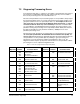
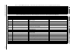
11 TB Tension On
12 TB Current Memory
13 TB Underwind
14 TB Slack Take Up
15 Level Det1 Output
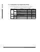
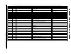
2
SPD LOOP REFERENCE (P.295) Final speed/voltage loop reference value
3
SPD LOOP FEEDBACK (P.296) Final speed/voltage loop feedback value after all scaling
4
SPD LOOP OUTPUT (P.299) Speed loop PI block output value 4095 at MAXIMUM CURRENT (P.007)
5
ARMATURE VOLTAGE (P.289) Armature voltage feedback value 4095 at MOTOR RATED ARM VOLTS (P.009)
6
CML REFERENCE (P.196) Amplitude-and rate-limited value of the selected CML
reference
7Average CML feedback CML feedback average over eight CML scans 4095 at MAXIMUM CURRENT (P.007)
8 Network Output Register 1 Value of the parameter selected by
NETW OUT REG 1
SELECT (P.902)
If no valid parameter value selected,
0=MOTOR SPEED IN RPM
9 Network Output Register 2 Value of the parameter selected by NETW OUT REG 2
SELECT (P.903)
If no valid parameter value selected,
0=armature voltage in volts
10 Network Output Register 3 Value of the parameter selected by
NETW OUT REG 3
SELECT (P.904)
If no valid parameter value selected,
0=armature current in amps*10 or amps
11 to 16 Tunable, Configurable and Status Data See table 7.4 on page 7-7.
17
LINE SPEED (P.188) Analog reference value output by the drive
18
DIAMETER/TAPER IN TP (P.192) Diameter/taper range input (TB 16, 17, 18) in counts
after gain and zero applied
DIAMETER, TAPER RANGE
19 TENSION SETPOINT IN (P.492) Digital value of the tension setpoint input (TB 50, 51)
after gain and zero applied
20
TENSION/DANCER FDBK (P.493) Digital value of the tension/dancer feedback input (TB
52, 53) after gain and zero applied
21
FREQ IN (P.491) Frequency input value (terminals 39, 40, 41 on I/O
Expansion board) after all scaling
4095 at full scale
22
OCL OUTPUT (P.848) Outer control loop output value RPM
23
OCL PARALLEL OUT (P.816) Output of the selected outer control loop for parallel
mode
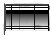
Table 7.3 – WebPak 3000 Register Map, Drop_1: Master Read Registers, BASIC and FULL Connections. Runtime Signal Data (Drive Output Data) (Continued)
Register Bit Parameter Name (Number) Description Settings
Runtime signal data are updated by the regulator every 10 msec.