
User Manual

FlexPak 3000 Drives: Alternate Register Map
6-11
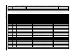
Table 6.8 – FlexPak 3000 Alternate Register Map, Drop_2: Master Read Registers, FULL Connection. Runtime Signal Data (Drive Output Data)
Register Parameter Name (Number) Description Settings
0 SPD SOURCE SELECT OUT (P.193) Selected speed/voltage loop reference value 4095 at TOP SPEED (P.011)
Runtime signal data are updated by the regulator every 5 msec, unless
FEEDBACK SELECT (P.200) is set to ARMATURE VOLT, in which case the update time is 10 msec.
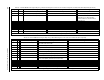
Table 6.9 – FlexPak 3000 Alternate Register Map, Drop_2: Master Read Registers, FULL Connection. Tunable, Configurable, and Status Data (Drive Output Data)
Register Bit Parameter Name (Number) Description Settings
1 ACCELERATION TIME (P.001) Min. time to accelerate from zero to TOP SPEED (P.011) seconds * 10
2
DECELERATION TIME (P.002) Min. time to decelerate from TOP SPEED (P.011) to zero seconds * 10
3
MINIMUM SPEED (P.003) Lowest operating speed RPM
4 MAXIMUM SPEED (P.004) Highest operating speed RPM
5 POSITIVE CURRENT LIM (P.005) Highest amount of current for the forward bridge % of MOTOR RATED ARM AMPS (P.008)
6
NEGATIVE CURRENT LIM (P.006) Highest amount of current for reverse bridge % of MOTOR RATED ARM AMPS (P.008)
7
TRIM RANGE (P.109) Amount the trim reference will affect the drive reference %
8
SPD LOOP PI PROP GAIN (P.211) Speed loop PI proportional gain gain * 100
9
SPD LOOP PI LEAD FREQ (P.212) Speed loop PI block lead break frequency radians/second * 100
10 Reserved
11
OCL RAMP OUTPUT (P.846) OCL reference S-curve block output 4095
12 Reserved
13
TOP SPEED (P.011) Highest running speed of motor RPM
14 JOG SPEED 1 (P.012) Operating speed while jogging RPM
15 JOG ACCEL/DECEL TIME (P.013) Minimum time in which jog reference can go from zero to
TOP SPEED (P.011) and from TOP SPEED to zero
seconds * 10
16
S-CURVE ROUNDING (P.014) Smoothing of the speed/voltage loop reference %
17
REVERSE DISABLE (P.015) Prevents speed/voltage loop ref. from going negative 0=OFF (bipolar ref); 1=ON (positive ref)
18
ANLG AUTO SIGNAL TYPE (P.100) Type of signal applied to analog auto reference input
0=0–10V; 1=±10V; 2=4-20mA; 3=10-50mA
19 ANLG AUTO GAIN ADJ (P.101) Scales analog auto reference signal gain * 1000
20
ANLG AUTO ZERO ADJ (P.102) Offset removed from analog auto reference zero
21
AUTO REFERENCE SELECT (P.103) Selects the type of auto reference 0= ANALOG; 1=FREQUENCY IN
22 ANLG MAN REF GAIN ADJ (P.104) Scales the analog manual reference gain gain * 1000
Tunable, configurable, and status data are updated by the regulator approximately every 600 msec.