
User Manual

FlexPak 3000 Drives: Alternate Register Map
6-9
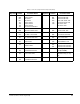
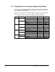
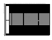
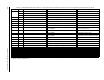
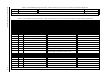
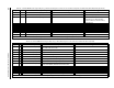
Table 6.5 – FlexPak 3000 Alternate Register Map, Drop_1: Master Write Registers BASIC and FULL Connections. Control/Reference Data (Drive Input Data)
Register Bit Parameter Name (Number) Description Settings
32 Sequencing control word Word containing drive sequencing and control bits
0 Run 0 to 1 transition to run
1 Stop 0=stop; 1=not stop
2 Fault reset 0 to 1 transition to reset
3 Jog 0 to 1 transition to jog; 0=stop
4 Fwd/Rev select 0=forward; 1=reverse
5
UNDERWIND ENABLE 0=DISABLED (overwind); 1=ENABLED
(underwind); (Default=0)
*
6 SPD LOOP PI RESET
0=OFF (enable) (default); 1=ON (reset)
*
7 Outer control loop enable 0=hold OCL in reset; 1=OCL enabled
8 Fault log clear and reset 0 to 1 transition to clear
9 Alarm log clear and reset 0 to 1 transition to clear
10 Alarm reset 0 to 1 transition to reset
11 Memory save 0 to 1 transition to save
12&13 Reserved
14 Tune/config input enable. What to read from the network. “Read all”
includes control/reference, tunable, and configurable inputs
0=read only control/reference inputs;
1=read all
15 Tune/config update synchronization flag (master write)
33 Network Reference Speed/voltage loop or
CML reference value when CONTROL SOURCE
SELECT (P.000)=NETWORK and AMX NETW REF SELECT (P.911)=0
4095 at
TOP SPEED (P.011)/MOTOR RATED
ARM VOLTS (P.009) or MAX CURRENT (P.007)
34 Network Input Register 1 Written by network master Read at
OIM or DCM (NETW IN REG 1, P.905)
35 Network Input Register 2 Written by network master Read at
OIM or DCM (NETW IN REG 2, P.906)
36 Network Input Register 3 Written by network master Read at
OIM or DCM (NETW IN REG 3, P.907)
37
FIELD REF REGISTER (P.513) Reference for the field current loop 4095 at MOTOR HOT FLD AMPS (P.510)
38
SPEED FEEDBACK GAIN Controls gain of the speed loop feedback path Gain * 1000 (1000 to 32000)
(Default=1000 (1.000))
*
*
This parameter is network-only. If the control source is changed from NETWORK to something else, this parameter is automatically reset to its default value.
39 SPD LOOP PI INIT VAL Initial value of speed loop PI block. This value is at the PI block
output when block is in reset. Block is in reset when drive is stopped
or bit 6 of sequencing control word (Drop_1, register 32) is set to 1.
4095 at MAXIMUM CURRENT (P.007)
(default=0)
*
Control/reference data are read by the regulator every 5 msec, unless FEEDBACK SELECT (P.200) is set to ARMATURE VOLT, in which case the update time is 10 msec.